


MTW European Type Trapezium Mill
Input size:30-50mm
Capacity: 3-50t/h
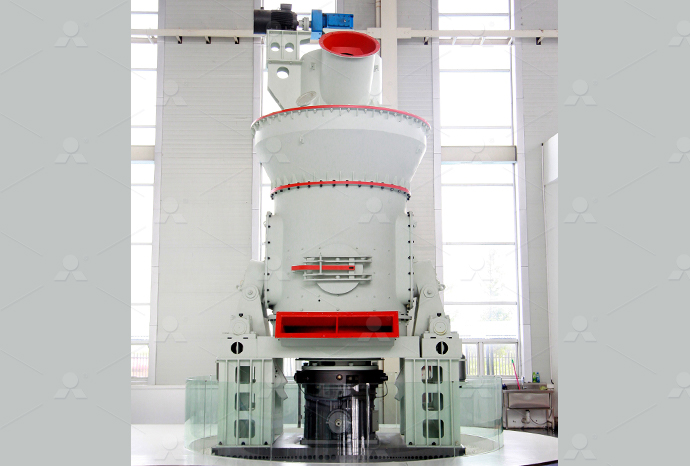
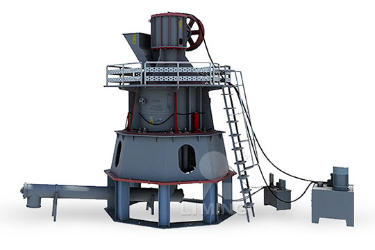
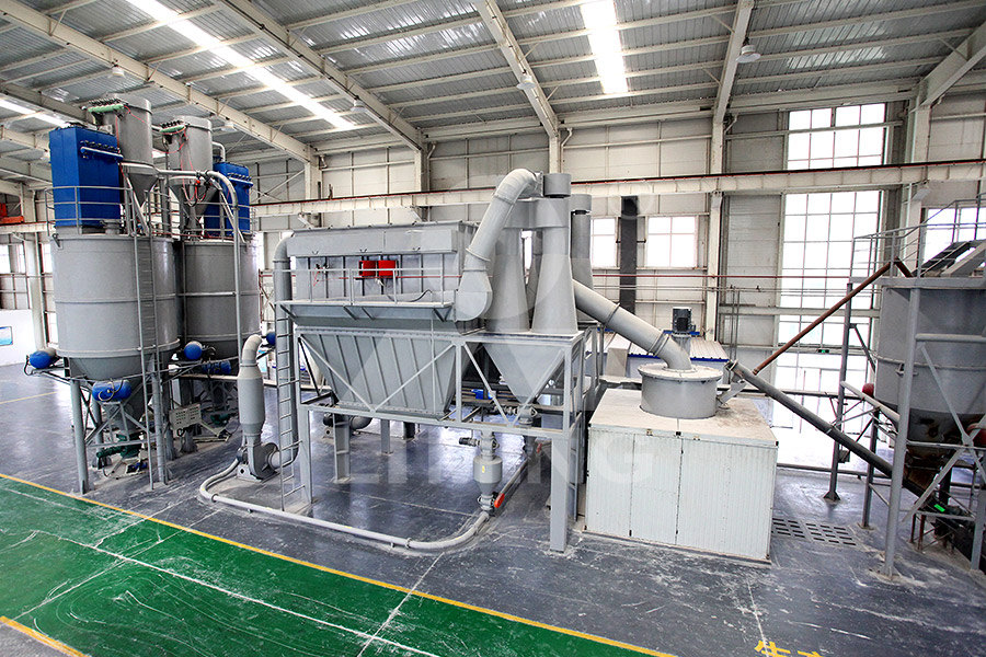
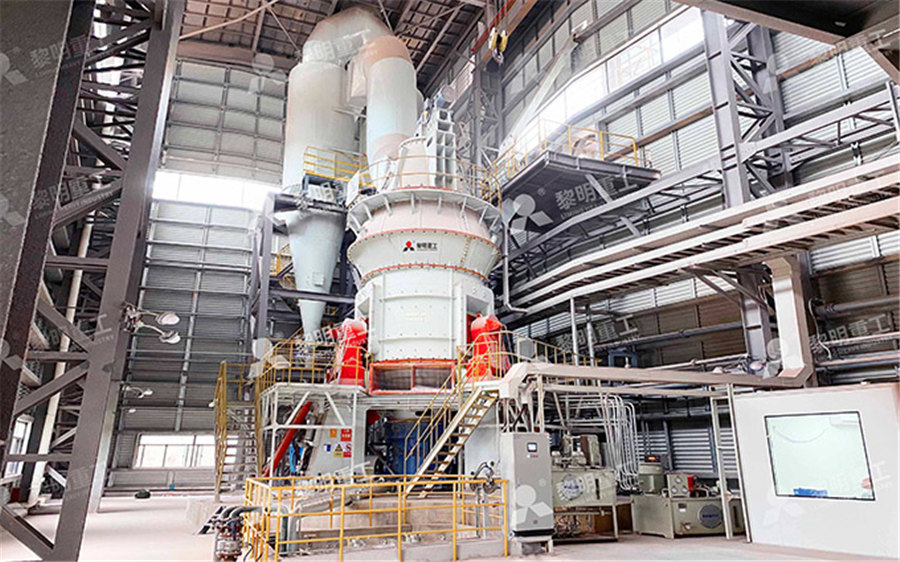
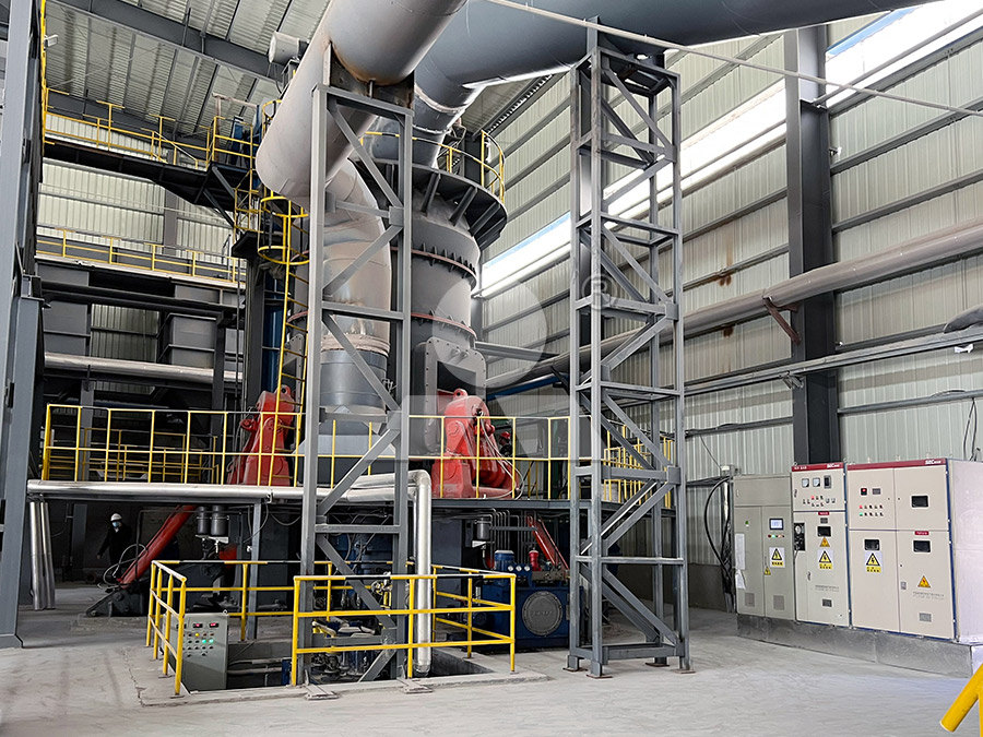
LM Vertical Roller Mill
Input size:38-65mm
Capacity: 13-70t/h
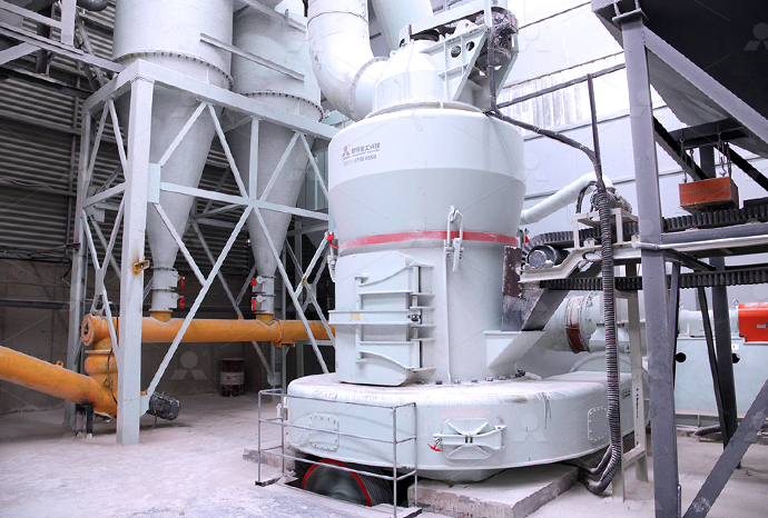
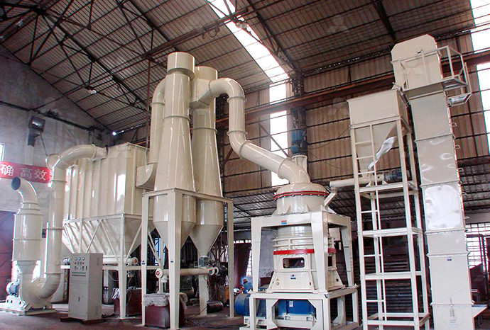
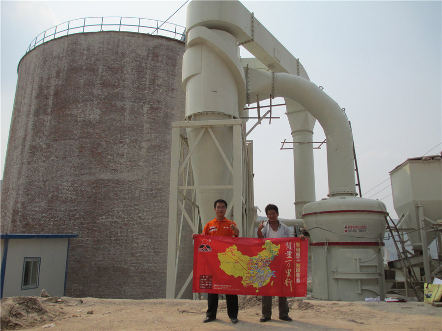
Raymond Mill
Input size:20-30mm
Capacity: 0.8-9.5t/h
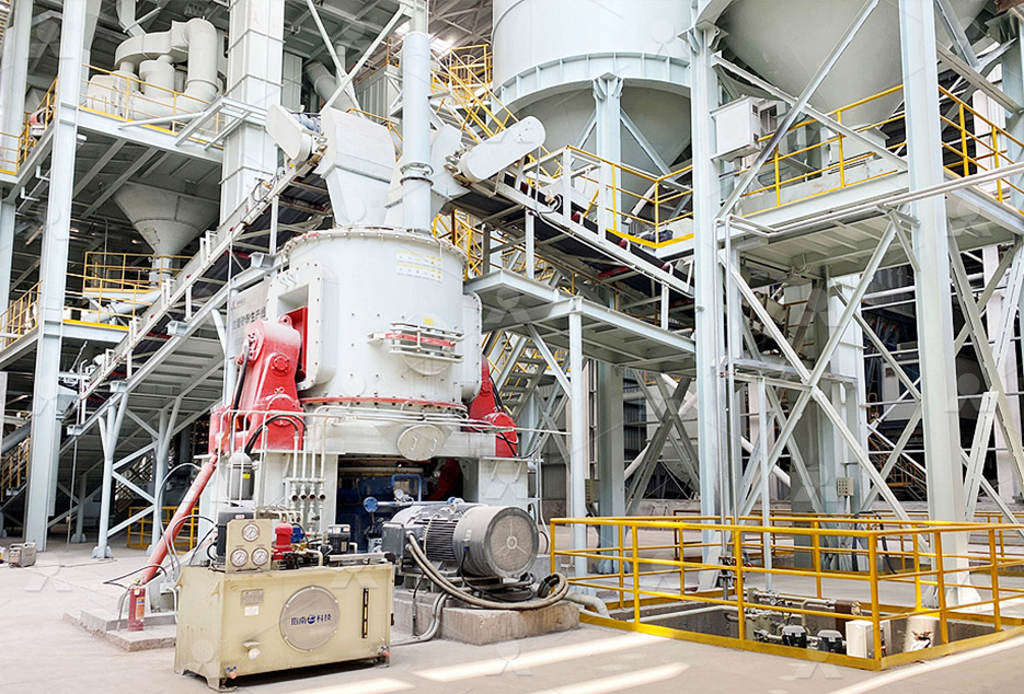
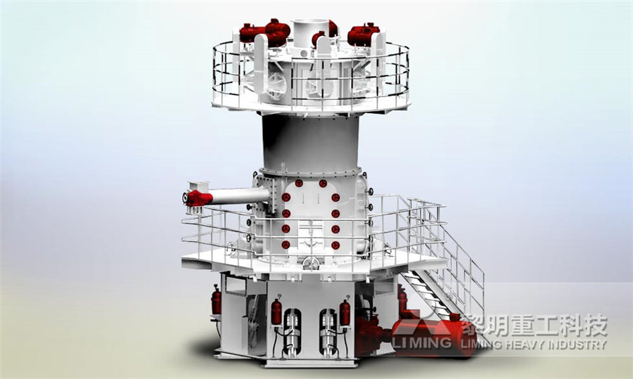
Sand powder vertical mill
Input size:30-55mm
Capacity: 30-900t/h
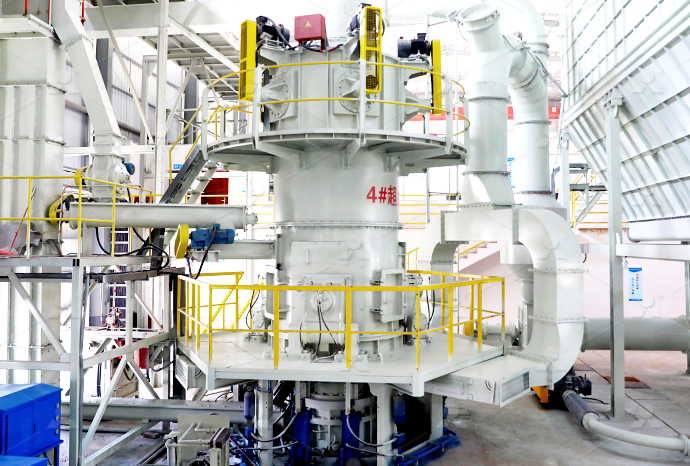
LUM series superfine vertical roller grinding mill
Input size:10-20mm
Capacity: 5-18t/h
MW Micro Powder Mill
Input size:≤20mm
Capacity: 0.5-12t/h

LM Vertical Slag Mill
Input size:38-65mm
Capacity: 7-100t/h

LM Vertical Coal Mill
Input size:≤50mm
Capacity: 5-100t/h
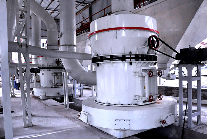
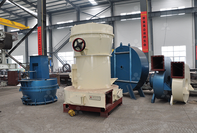
TGM Trapezium Mill
Input size:25-40mm
Capacity: 3-36t/h
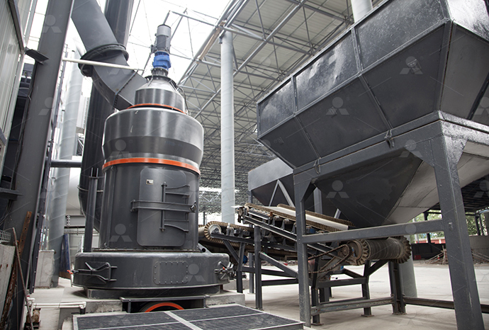
MB5X Pendulum Roller Grinding Mill
Input size:25-55mm
Capacity: 4-100t/h
Straight-Through Centrifugal Mill
Input size:30-40mm
Capacity: 15-45t/h
Hydraulic grinding production line diagram
.jpg)
3 industrial hydraulic circuits shapping, milling, drilling
2021年3月23日 The document describes several hydraulic circuits used in industrial machinery It summarizes the hydraulic circuits for a milling machine, shaper machine, surface grinder, hydraulic press, hydraulic power steering, After a thorough investigation of all items of information and data collected in various ways, this paper identified several problems in the grinder, the flowline production system, and the Balancing of the Production Line Process in the Manufacturing of Surface grinding is used to produce flat accurate surfaces This can be illustrated by considering the grinding of all surfaces of the component shown in Fig 716 It is important to first establish CHAPTER 7: SURFACEE GRINDINGThank you for your purchasing this high precision Universal Cylindrical Grinding Machine We believe that this machine is capable of meeting your requirement and to make your product G32P(A)CNCmanual(Eng)A Sharp Industries
Cement Manufacturing Process INFINITY FOR
The process is called a drying /grinding process, where most of the material/product is transported pneumatically by drying gases Grinding: the material is ground between rollers and grinding table while passing from the A Piping and Instrumentation Diagram (PID or PID) is a detailed diagram in the process industry which shows process equipment together with the instrumentation and control devices It is Piping and instrumentation diagram Wikipedia2021年7月6日 This study produces the future value flow diagram to optimize the hand grinder production line In this survey, industrial engineering (IE) methodologies helped improve the Balancing of the Production Line Process in the Manufacturing of Download scientific diagram Figure: Schematic illustration of a horizontalspindle surface grinder from publication: PRODUCTION PROCESS 08 [ ROLLING OPERATION, FORGING Figure: Schematic illustration of a horizontalspindle surface
Automatic Production Line of Resin Grinding Wheel
Cosmos Press’s Automatic Production Line of Resin Grinding Wheel is composed of packing hydraulic press, prepress hydraulic press, hotpress hydraulic press (can be equipped with 2 sets), demoulding hydraulic press, conveying device, finished thermal insulation box, mold cooling device and mold preheating deviceFigure 122: Hydraulic system pictorial diagram Cutaway Diagrams Cutaway diagrams (Figure 123) show the internal working parts of all fluid power components in a system The diagrams include controls and actuating Basic Diagrams and Systems Engineering LibraryHydraulic Circuit Diagram with Explanation In a hydraulic system, a circuit diagram is a graphical representation of the different components and connections that make up the system It shows how the fluid flows through the system and how the different components interact with each other to perform specific tasksUnderstanding Hydraulic Circuit Diagrams: Explained in Detailc) Hydraulic shaper The ram of a hydraulic shaper is connected to a piston Oil at high pressure is pumped to the cylinder of the hydraulic system As the oil pushes the piston, the ram reciprocates Hydraulic shapers are high power machines and are used for heavyduty work 2 According to the position and travel of the ram: a) Horizontal shaperShaper Machine – Types, Parts, Working, Operations, Diagram
Training Basic Hydraulics Parker Hannifin
Hydraulic Symbols 7 Dump Pumps 8 Gear Pumps 9 Accumulators 10 Directional Control Valves 11 Double Acting Cylinders 12 Fixed Displacement Motor 13 In Cab Control Valves 14 Dump Truck 2 Line System 44 Dump Truck 3 Line System 45 QDB Manual Spreader Valve with Power Beyond 46 PSM 1000 Spreader Valve No In Cab Hydraulics 47 PSM 2021年5月5日 A grinding machine is a production machine tool used in the manufacturing industry in which the grinding wheel is attached in the tool post and the workpiece is fixed to the work table and when the operation starts it removes the unwanted material to get the desired surface finish, Hydraulic clutch: Definition, Grinding Machine: Definition, Parts, Working Principle, Operation Grinding balls production line produces grinding media, grinding media balls from dia30mm to dia150mm with different compositions Automatic grinding balls production line is the assembly line with sand molding device, tilting type pouring system, iron mold opening and closing position, flipping down material position, etcAutomatic casting grinding balls production line2Production slotting machine General production machine; Common type; Mechanism – Slotted disc, Connecting ram; 3Precision Tool Room slotting machine Light duty machine; High speed; Slotter Machine Diagram : parts of slotter machine Principal parts of a Slotting machine : The figure shows a slotter and its various partsSlotter Machine – Types, Parts, Operations, Diagram, Specification
.jpg)
Understanding the Surface Grinding Machine: An InDepth Diagram
The diagram of a surface grinding machine showcases various components and their functions The main components include a base, column, wheel head, table, and reciprocating table The base provides a stable foundation for the machine, while the column supports the wheel head and houses the hydraulic control system16 During grinding and before the grinding wheel stops rotating after work is finished, do not attempt to clean the shavings of the work piece or move the work piece 17 When taking off the grinding wheel, use a flange remover to detach it Do not use any method that involves pounding the grinding wheel This could result in damage to the INSTRUCTION MANUAL FOR PRECISION SURFACE GRINDER Types Of Surface Grinding machine with Diagram Explained Surface grinding machine: This primarily production type machine often uses two or more grinding heads thus enabling both roughing and finishing in one rotation of the Types Of Surface Grinding machine with Diagram PDF On May 31, 2013, Sarvilkumar Kapadiya and others published PRODUCTION PROCESS ANALYSIS ON MANUFACTURING OF HYDRAULIC GEAR PUMP Find, read and cite all the research you need on ResearchGatePRODUCTION PROCESS ANALYSIS ON
Dinanath Precision Clampings
TOOL GRINDING Hydraulic expanding mandrels also find application for tool manufacturing The diagram shows hydraulic mandrel for carbide end mill manufacturing Carbide blank is clamped on mandrel within 0003 mm on 4*D 2022年12月1日 Hydraulic control schematic diagram Working principle: First, open the main switch and connect the oil circuit The signal obtained by the twoposition, threeway reversing valve is placed in the Design of hydraulic pneumatic control system for rail grinding carThe No 2 Universal Tool and Cutler Grinding machine is a larger machine, having a swing of 12" over the table and can be arranged for either hand or hydraulic traversing of the table The latter arrangement is particularly useful where surface jobs or INSTRUCTION MANUAL VintageMachineryThe hydraulic circuit for a milling machine is comparatively different from the hydraulic circuit of the surface grinding machine and hydraulic circuit of the shaper machineThis is because the table movement in milling operation is comparatively slower Also, the different feeds or you can say adjustable feeds are required for milling different types of workHydraulic Circuit for Milling Machine Explained In Details
.jpg)
Cocoa Processing Flow Chart (From Bean To Powder)
2022年11月12日 The cocoa butter is pressed using a hydraulic press First, put the cocoa paste into a press filter bag, and press it under high pressure In just 10 minutes, the oil content in the cocoa cake can reach about 12% We get brightly colored cocoa butter 4 Crushing and Grinding – Cocoa PowderThe hydraulic circuit for surface grinding machine utilizes a power pack to supply pressurized oil, one pilotoperated direction control valve which decides the direction of the flow of pressurized oil and a doubleacting cylinder with the double piston rodHydraulic Circuit for Surface Grinding Machine Engineering ArenaA piping and instrumentation diagram displays the piping components (for example equipment, valves, reducers and so on) of an actual physical process flow and is often used in the engineering projects, such as setting up steam boilers, heat exchangers, electric boilers and more To read a piping and instrumentation diagram, simply break down the overall diagram What is a Piping and Instrumentation Diagram (PID)2023年8月3日 Characteristics of hydraulic systems: Advantages: 1 The hydraulic transmission device operates smoothly and can move steadily at low speeds When the load changes, its movement stability is relatively stable, and it can easily achieve stepless speed regulation during movement, and the regulation ratio is large, generally up to 100:1, and the maximum can A Comprehensive Guide to Hydraulic Systems: Principles,
.jpg)
Diagram of the 80 MN hydraulic forging press: A1
Diagram of the 80 MN hydraulic forging press: A1main (working) cylinder, A2, A3return cylinders, V14/4/ directional control valve, Pwater pump station, Ahighpressure water accumulators, Tr • Interpret hydraulic system symbols and circuit diagrams • Describe techniques for energy saving in hydraulic systems Introduction Typical hydraulic circuits for control of industrial machinery are described in this lesson Graphical hydraulic circuit diagrams incorporating component symbols are used to explain the operation of the circuitsINDUSTRIAL HYDRAULIC CIRCUITS IDCOnlineDirectional Control Valves Manual: Shown as a valve symbol with an actuator lever; Solenoid: Indicated by a square with a diagonal line and a circle at one end, representing the solenoid actuator; Pilotoperated: Combines basic valve Hydraulic Schematic Symbols Piping Technology Hydraulics Systems Diagrams and Formulas for a front end loader, winch, logsplitter, and other useful formulas Hydraulics Systems Diagrams and Formulas for a front end loader, A return line filter is used to prevent contamination Winch The diagram shows a winch powered by a hydraulic motorHydraulics Systems Diagrams and Formulas Cross MFG
Hydraulic cylindrical grinding machine Download Scientific Diagram
Download scientific diagram Hydraulic cylindrical grinding machine from publication: Experimental investigation of the effects of process parameters on material removal rate using Taguchi Product Name: GGBS Production Line / Slag Mill Capacity: 3,6000 – 1,000,000 T/Y Grinding Systems: VRM system, Ball mill open circuit system, Ball mill closed circuit system, Roller press final grinding systemGGBS Production Line Slag Mill for Slag Powder Grinding AGICOA first check can be done by looking at the utilization of the individual elements of the design Present Method Figure 2 : Layout Diagram of Company by Present Method 50 Mechanical Engineering: An International Journal ( MEIJ), Vol 1, No 1, May 2014 This is present line diagram of Company It represents all the process step by stepPRODUCTION PROCESS ANALYSIS ON MANUFACTURING OF HYDRAULIC maintenance hydraulic diagram jaw crusher – Grinding Mill China Hydraulic Cone Crusher; cs series Cone Crusher; HighEfficiency Nov 11, 2003 FIG 5 is a hydraulic circuit diagram of a jaw crusher according to Hydraulic Cone Crusher + Diagram
(PDF) A REVIEW STUDY IN TROUBLESHOOTING OF HYDRAULIC
2022年12月31日 Behind every hydraulic system there exists critical components that influence power production capacity of the factory is 100,000 line; it can also be spinon, inline, or tank 2024年8月4日 Fig3 80,000 Ton Die Forging Press The 80,000ton dieforging hydraulic press stands 27 meters tall on the ground and 15 meters underground, making it a total height of 42 meters and a total weight of 22,000 tons, thereby earning its title as the world’s most powerful and strongest hydraulic pressHydraulic Press Machine 101: Everything You Need to Know H Raw material grinding/drying 13 I Clinker cooler 14 J Clinker piles 15 K Clinker transfer 16 L Clinker grinding 17 M Cement silos 18 N Cement load out 19 O Raw mill feed belt 24 P Raw mill weigh hopper 25 Q Raw mill air seperator 26 R Finish grinding mill feed belt 27 S Finish grinding mill weight hopper 28116 Portland Cement Manufacturing US Environmental Calculate the speed, pressure and loadcarrying capacity of hydraulic circuits Evaluate the performance of hydraulic circuits using various hydraulic elements 11 Introduction A hydraulic circuit is a group of components such as pumps, actuators, control valves, conductors and fittings arranged to perform useful workLecture 24 HYDRAULIC CIRCUIT DESIGN AND ANALYSIS
Parts for crushing and screening equipment
equipment includes more than 30 thousand units of production: shafts, bushings, gears, bearings, frame parts, linings, crushing segments, jaw plates, etc Element is not limited to the product line of one manufacturer and offers spare parts for the equipment of most existing brands in 2021年7月6日 So many production factories in Africa are still using manual production methods A few of them have introduced a semiautomated production process, wasting lots of time trying to balance the production line As a result, it is essential to investigate the production line balance problem and optimize the production line layoutBalancing of the Production Line Process in the Manufacturing Download scientific diagram Schematic diagram of the equipment on a hydraulic fracturing site The flow path of the fracfluid is from right to left of the schematic In this schematic the red Schematic diagram of the equipment on a hydraulic fracturing Figure 27 Simple Hydraulic Power System Figure 28 Line Diagram of Simple Hydraulic Power System With an understanding of the principles involved in reading fluid power diagram, any diagram can be interpreted Figure 29 shows the kind of diagram that is likely to be encountered in the engineering fieldHydraulic and Pneumatic PID Diagrams and Schematics
pasar copper refinery process flow diagram chinagrindingmill
Grinding Solutions Grinding is the required process when size reduction of below 520 mm is neededGrinding is a powdering or pulverizing process, and it can use three methods Crushing Solutions From large primary jaws and gyratories to cones and impacts for tertiary and quaternary finishing, Gulin has the right crusher and crusher parts » Copper mining portable 2023年7月19日 Hydraulic Shaping Machine With these sorts of shaper machines, the hydraulic system provides the reciprocating action of the ram The hydraulic shaper utilises highpressure oil This is provided through a system which is understood by the hydraulic circuit for the shaper machine given below Fig 4: Hydraulic Circuit for Shaper MachineShaping Machine: Learn the working principle, operations typesVP Online is the best process flow diagram software because it offers a rich set of powerful editing features and symbols that suit different industries and purposes You can easily map out a process flow with draganddrop, and share your design with Process Flow Diagram Software Visual ParadigmThe vertical roller mill (VRM) is a type of grinding machine for raw material processing and cement grinding in the cement manufacturing processIn recent years, the VRM cement mill has been equipped in more and more cement plants around the world because of its features like high energy efficiency, low pollutant generation, small floor area, etc The VRM cement mill has a Vertical Roller Mill Operation in Cement Plant