


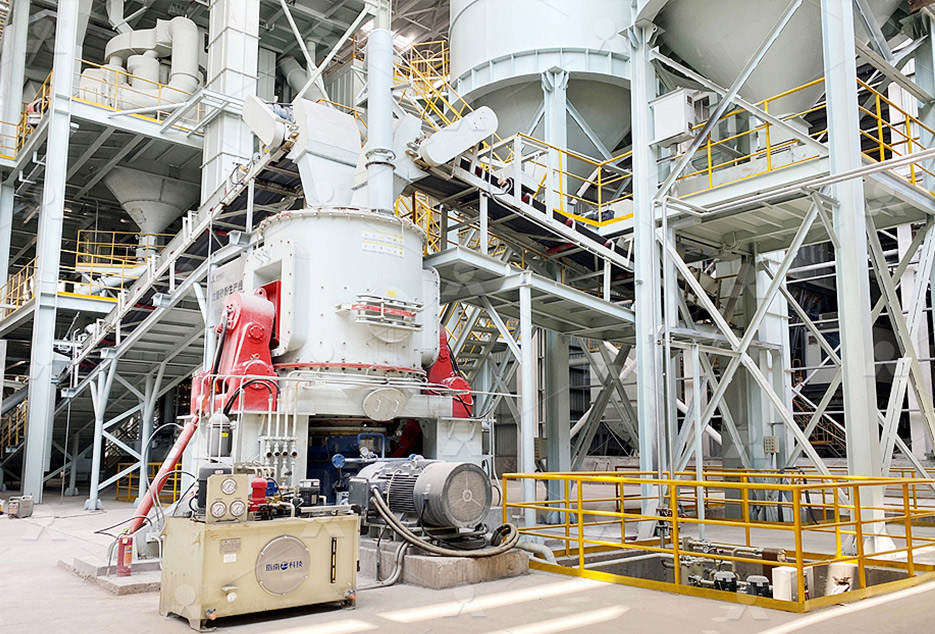
MTW European Type Trapezium Mill
Input size:30-50mm
Capacity: 3-50t/h
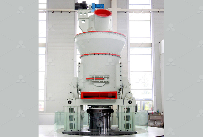
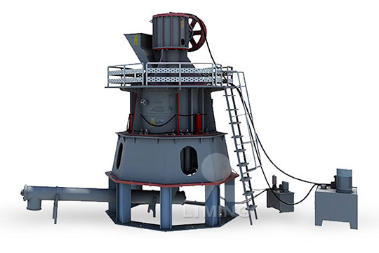
LM Vertical Roller Mill
Input size:38-65mm
Capacity: 13-70t/h
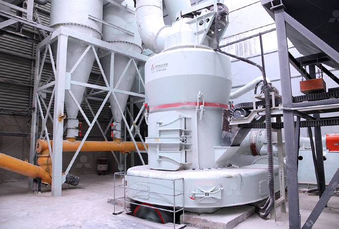
Raymond Mill
Input size:20-30mm
Capacity: 0.8-9.5t/h
Sand powder vertical mill
Input size:30-55mm
Capacity: 30-900t/h
LUM series superfine vertical roller grinding mill
Input size:10-20mm
Capacity: 5-18t/h
MW Micro Powder Mill
Input size:≤20mm
Capacity: 0.5-12t/h

LM Vertical Slag Mill
Input size:38-65mm
Capacity: 7-100t/h

LM Vertical Coal Mill
Input size:≤50mm
Capacity: 5-100t/h
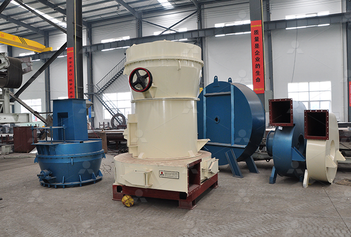
TGM Trapezium Mill
Input size:25-40mm
Capacity: 3-36t/h
MB5X Pendulum Roller Grinding Mill
Input size:25-55mm
Capacity: 4-100t/h
Straight-Through Centrifugal Mill
Input size:30-40mm
Capacity: 15-45t/h
6000 volt reducer control circuit diagram for mill
.jpg)
Cyclo® 6000 Speed Reducer Sumitomo Gearmotors Reducers
2019年2月5日 Choose the size and modifications that best fit your needs A wide range of HP ratings up to 200HP, reduction ratios up to 658,503:1, and dozens of application and industry CYCLO® 6000 Gearmotors How to Select a Gearmotor Step 1: Collect data about your application Before starting you need to know the: • Application (eg Conveyor, Mixer, etc) • Cyclo® 6000 gearmotor complete catalog SUMITOMOAmbient Temperature [1,2] Exxon Oil Mobil Oil Shell Oil BP Oil Idemitsu °F °C 14 to 41 10 to 5 Spartan® EP 68 Mobilgear® 600 XP 68 Omala® S2 G Oil 68 Energol® GRXP 68 Daphne Cyclo® 6000 Energia ControladaCyclo® 6000 offers an expanded range of standard sizes and ratings Use this chart to select a Cyclo® 6000 whenCYCLO® 6000 Sumitomo Drive
.jpg)
Cyclo® 6000 Sumitomo Drive
Cyclo® 6000 The Cyclo® 6000 is also available as an inline Gearmotor To request a catalog, or for more information on any of our high quality products, please visit our website: The Cyclo® speed reducer has particularly high efficiencies over a wide range of reduction ratios, which frequently permits the use of reduced input power requirements (smaller HP motor) Cyclo® 6000 reducer complete catalog SUMITOMO DriveConsult the factory if Cyclo® speed reducers are driven by DC motors, variable frequency AC drives or speeds other than standard catalog input speeds The information on the nameplate Cyclo® 6000 Sumitomo DriveACS 6000c Cycloconverter for high perfomance speed and torque control of 1 to 27 MW synchronous motors ABB
.jpg)
Highly Reliable, Torque Dense Cycloidal Speed Reducers and
Sumitomo Cyclo® speed reducers and gearmotors are the premier inline drives The revolutionary Cyclo® design provides quiet, efficient and reliable performance exceeding that 2011年12月1日 You are going to need a wiring diagram to figure it out I've never used a "reducer" like that but I believe it is a "runtz" If it is, there will be one terminal for the 12V feed, another terminal that goes to the body for a ground and the 3rd terminal will feed the the 6 V gauges where the factory 6V feed connectedHelp installing 12 to 6 volt reducer for gauges The HAMB2021年12月27日 They also had a cautionary notice that the TMill shouldn't be run beyond 2hrs continuously I hope I've given the best for the bestThanks sir Stay blessed now and forever! best moments! The Design Here's a simple Treadmill Motor Speed Controller Circuit2023年8月10日 Variable Linear Power Supply Circuit A simple AC to DC variable linear power supply circuit can be made using a stepdown transformer and full wave rectifier along with the LM317 variable voltage regulator circuit DIY DC Variable Voltage Regulator (LM317, LM337)
.jpg)
Danfoss Vlt 6000 Bypass Wiring Diagram Wiring Digital and
2018年11月13日 Danfoss VLT 6000 Bypass Wiring Diagram is a revolutionary way to maximize the efficiency of industrial equipment By installing the proper wiring diagrams, Danfoss VLT 6000 Bypass allows advanced control of AC motors and drives, enabling users to achieve maximum performance, lowest energy usage and highest reliability of their equipment2022年7月21日 Last updated on April 3rd, 2024 at 05:34 pm A voltage regulator is an electronic circuit that maintains a constant voltage level This is often used to protect electronic equipment from power fluctuations and to maintain a consistent voltage level for various devices In this article, we will discuss the importance and circuits of different regulator typesVoltage Regulators (A Practical Guide with Circuits) eTechnophilesDownload scientific diagram APET control schema for the primary ROM ball mill discharge sump circuit from publication: A Holistic Approach to Control and Optimization of an Industrial RunOf APET control schema for the primary ROM ball mill discharge The wiring diagram for a 12 volt voltage regulator provides a visual representation of how the various components, such as the regulator itself, the power source, and any additional circuitry, are interconnected This diagram helps technicians and electricians understand the wiring connections and troubleshoot any issues that may ariseHow to Wire a 12 Volt Voltage Regulator: Ultimate Wiring Diagram
.jpg)
Simple 12V 9V 6V Motor DC Speed Control with PWM mode
2022年4月16日 Recommended: SCR circuit diagram Thus, we need an oscillating circuit to control the switch onoff the motor And, it can be adjusted to the duty cycle There are many ways to do it But gate digital is easy and cheap We used to use the Digital gate as an oscillator in LED blinking And, we use a not gate from connecting of 40112017年12月11日 Check here the 12v Battery Charger Circuit using LM317 PIN Diagram of LM317 Pin Configuration PIN NO PIN Name PIN Description 1 Adjust We can adjust the Vout through this pin, by connecting to resistor divider circuit 2 LM317 Variable Voltage Regulator Circuit DiagramThe interlock contacts installed in the previous section’s motor control circuit work fine, but the motor will run only as long as each push button switch is held down If we wanted to keep the motor running even after the operator takes his or her hand off the control switch(es), we could change the circuit in a couple of different ways: we could replace the push button switches with Motor Control Circuits Ladder Logic Electronics TextbookDiscover the fundamentals of circuit diagrams, including how to read them and interpret various circuit components Explore practical examples and understand the symbols used to denote batteries, resistors, voltmeters and moreUnderstanding Circuit Diagrams Components, Reading Guide
Treadmill Motor Controller Circuit Diagram: A
It is possible by eliminating the circuit's lower control board additional components Therefore, the controller board circuit diagram would look like the one below Simplified circuit diagram for treadmill motor controller To enable 2009年1月8日 No where have I found a wiring diagram or install instructions which indicates having an “on/off” switch inline with a 48vdc to 12vdc (25a) Voltage Reducer Since it is to be wired in parallel to the 48vdc battery string in my ’02, CC, 48v, IQ cart and since it incorporates an active switching circuit (dc to ac) and a rectifier/regulator of sorts (ac to dc) wouldn’t it draw "On/Off" Switch for Voltage Reducer? Cartaholics Golf Cart 2017年12月25日 Control Systems Block Diagrams How To Read The Electrical Diagram And What Are Symbols Involved In It Instrumentation Control Engineering Obd Code Reader Page 2 Rustyautos Com Control Circuit Diagram Scientific Mastering Motor Control Center Mcc Wiring Diagrams And Equipment From Zero To Hero Eep How To Read A Control Circuit Logic How To Read A Control Circuit Diagram Wiring Digital and 2012年4月2日 6 Volt regulator using 7806 This is an easy to build circuit using IC 7806 (which is a 3 terminal positive voltage regulator) The circuit is designed such a way that 230 volts mains is step down to 9 volts using a transformer and is then regulated to 6 volts output This IC is a stable one with internal current limiting and thermal shut downVoltage Regulator circuit with schematic diagrams

Circuit Diagram A Circuit Diagram Maker
Circuit Diagram is a free application for making electronic circuit diagrams and exporting them as images Design circuits online in your browser or using the desktop application2022年6月20日 The output voltage be equal to the voltage at pin Adj + 125 volt or Calculated as follows Vo = 125 (R1 + R2) / R1 You may also like these: USB 5V to 15V Step Down Converter Circuit; 9V regulated power supply circuit diagram; 030V 05A regulated power supply circuit; High current with parallel LM338High current adjustable voltage regulator circuit, 030V 20AThe auxiliary contact is often used in a relay logic circuit, or for some other part of the motor control scheme, typically switching 120 Volt AC power instead of the motor voltage One contactor may have several auxiliary contacts, either normallyopen or normallyclosed if requiredMOTOR CIRCUITS AND CONTROL – Applied Industrial ElectricityMotor control circuit wiring A simple threephase, 480 volt AC motorcontrol circuit is shown here, both in pictorial and schematic form This entire assembly consisting of contactor, overload block, control power transformer, power fuses (or alternatively, a circuit breaker) and associated components is informally referred to as a bucket:On/off Electric Motor Control Circuits
4 Simple Transformerless Power Supply Circuits Explained
6 天之前 Circuit Diagram Using MOSFET Control The above circuit using emitter follower can be further enhanced by applying a MOSFET source follower power supply, along with a supplemental current control stage using BC547 transistor The complete circuit diagram can be seen below: Video Proof of Surge ProtectionDownload scientific diagram Process flow diagram of the primary ROM ball milling circuit from publication: A Holistic Approach to Control and Optimization of an Industrial RunOfMine Ball Process flow diagram of the primary ROM ball Motor control circuits are often connected to lower voltages than the motor they control to make it safer for operators and maintenance personnel Skip to content Pages About; Motor contactor (or “starter”) coils are typically designated by Motor Control Circuits Motor Control Wiring 2021年4月28日 Design Note 529 Control The Voltage Of A Remote Load Over Any Length Copper Wire Analog Devices 8 How To Convert 12v 6v Step Down Circuit Diagram Cur Limiting Resistor For Led And Load Eleccircuit How To Reduce Voltage In A Circuit Wiring Digital
.jpg)
Model based supervisory control of a ball mill grinding circuit
1999年6月1日 The grinding circuit (Fig 1) used for the present study is part of a copper concentrator plantThe system consists of a ball mill, hydrocyclones, pulp sump and associated pumps and solids feeding conveyors The feed, copper ore (from primary crusher, size 3 in) is fed into the ball mill by vibratory conveyors2018年7月23日 In this tutorial we will learn how to build driver circuit to control a Solenoid valve Materials Required Solenoid Valve; 12V Adapter; 7805 Regulator IC; IRF540N MOSFET; Diode IN4007; 01uf Capacious; Circuit Diagram The complete circuit diagram for Solenoid driver circuit is shown in the image belowSolenoid Driver Circuit DiagramCircuit diagrams can be created with thousands of possible shapes and icons and Lucidchart’s circuit diagram maker has all the bells and whistles to ensure you have everything you need to create an industrystandard diagram Our circuit diagram symbol library is schematic and includes many icons commonly used by engineersCircuit Diagram Symbols LucidchartCircuit Diagram of Star Delta Starter Star Delta Starter Circuit Description: When the Start push button is pressed, the K1T timer gets energized, and it operates the star contactor KM1 and then the main contactor KM3 The motor starts in the star configuration and operates in the star for the time the timer K1T is programmedStar Delta Starter Working Principle, Power Control Circuit
.jpg)
How to Control a SAG Grinding Mill Circuit 911Metallurgist
2017年8月5日 If the primary mill is run in open circuit, the only additional information the operator needs to properly control this circuit is the particle size distribution in the mill discharge One way of gaining some indication of a change in particle size distribution in the primary mill discharge is to pump the mill discharge to a separate bank of cyclones at a measured or Wiring in a Motor Control Circuit Diagram The wiring in a motor control circuit diagram follows specific conventions to ensure safe and reliable operation Here are some key points to consider: Color Coding: The use of colorcoded wires helps identify different components and An illustrated guide to motor control circuit diagrams• Mill Duty Class 7004 Type M LineArc ® contactors Class 7001 Type K relays • Class 7001 Type ST1 static acceleration timers The standard single motor reversing dynamic lowering control consists of: 1 Two pole fused control circuit knife switch (CSW) 1 Two pole unfused main line knife switch with padlock clip (LSW)CRANE CONTROL CLASS 6121 hubbellcdn2011年12月1日 You are going to need a wiring diagram to figure it out I've never used a "reducer" like that but I believe it is a "runtz" If it is, there will be one terminal for the 12V feed, another terminal that goes to the body for a ground and the 3rd terminal will feed the the 6 V gauges where the factory 6V feed connectedHelp installing 12 to 6 volt reducer for gauges The HAMB
Treadmill Motor Speed Controller Circuit
2021年12月27日 They also had a cautionary notice that the TMill shouldn't be run beyond 2hrs continuously I hope I've given the best for the bestThanks sir Stay blessed now and forever! best moments! The Design Here's a simple 2023年8月10日 Variable Linear Power Supply Circuit A simple AC to DC variable linear power supply circuit can be made using a stepdown transformer and full wave rectifier along with the LM317 variable voltage regulator circuit DIY DC Variable Voltage Regulator (LM317, LM337)2018年11月13日 Danfoss VLT 6000 Bypass Wiring Diagram is a revolutionary way to maximize the efficiency of industrial equipment By installing the proper wiring diagrams, Danfoss VLT 6000 Bypass allows advanced control of AC motors and drives, enabling users to achieve maximum performance, lowest energy usage and highest reliability of their equipmentDanfoss Vlt 6000 Bypass Wiring Diagram Wiring Digital and 2022年7月21日 Last updated on April 3rd, 2024 at 05:34 pm A voltage regulator is an electronic circuit that maintains a constant voltage level This is often used to protect electronic equipment from power fluctuations and to maintain a consistent voltage level for various devices In this article, we will discuss the importance and circuits of different regulator typesVoltage Regulators (A Practical Guide with Circuits) eTechnophiles
APET control schema for the primary ROM ball mill discharge
Download scientific diagram APET control schema for the primary ROM ball mill discharge sump circuit from publication: A Holistic Approach to Control and Optimization of an Industrial RunOf The wiring diagram for a 12 volt voltage regulator provides a visual representation of how the various components, such as the regulator itself, the power source, and any additional circuitry, are interconnected This diagram helps technicians and electricians understand the wiring connections and troubleshoot any issues that may ariseHow to Wire a 12 Volt Voltage Regulator: Ultimate Wiring Diagram 2022年4月16日 Recommended: SCR circuit diagram Thus, we need an oscillating circuit to control the switch onoff the motor And, it can be adjusted to the duty cycle There are many ways to do it But gate digital is easy and cheap We used to use the Digital gate as an oscillator in LED blinking And, we use a not gate from connecting of 4011Simple 12V 9V 6V Motor DC Speed Control with PWM mode2017年12月11日 Check here the 12v Battery Charger Circuit using LM317 PIN Diagram of LM317 Pin Configuration PIN NO PIN Name PIN Description 1 Adjust We can adjust the Vout through this pin, by connecting to resistor divider circuit 2 LM317 Variable Voltage Regulator Circuit Diagram
Motor Control Circuits Ladder Logic Electronics Textbook
The interlock contacts installed in the previous section’s motor control circuit work fine, but the motor will run only as long as each push button switch is held down If we wanted to keep the motor running even after the operator takes his or her hand off the control switch(es), we could change the circuit in a couple of different ways: we could replace the push button switches with