


MTW European Type Trapezium Mill
Input size:30-50mm
Capacity: 3-50t/h
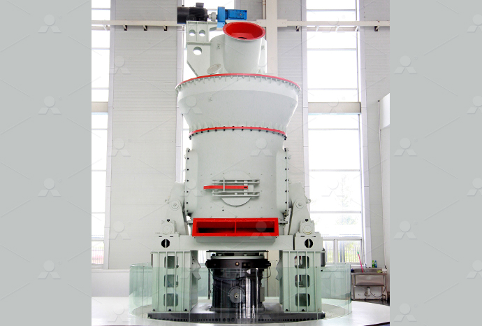
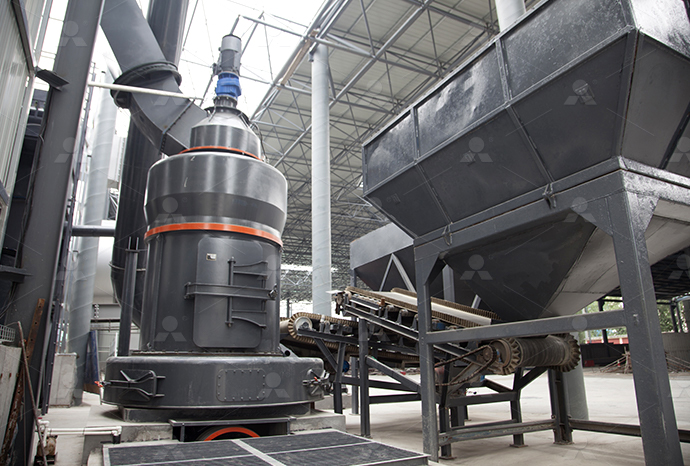
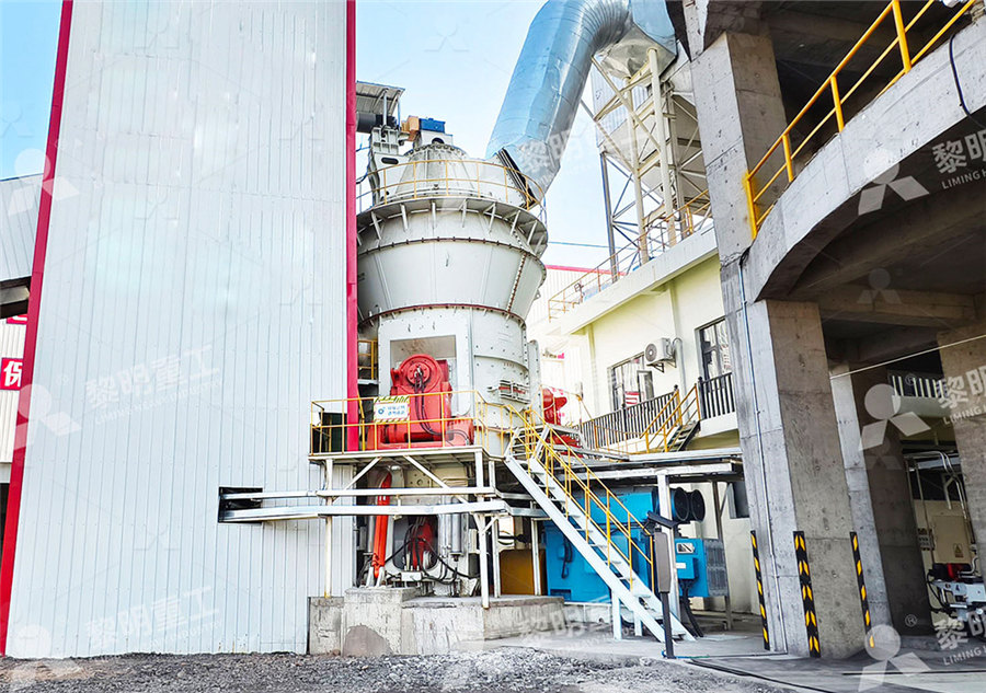
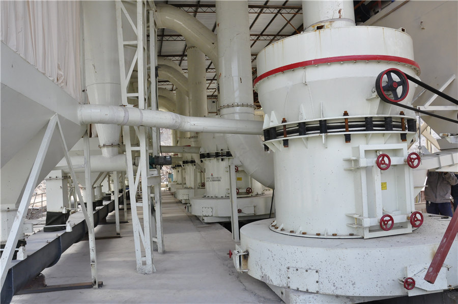
LM Vertical Roller Mill
Input size:38-65mm
Capacity: 13-70t/h
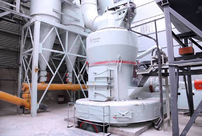
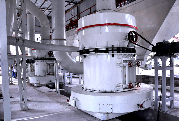
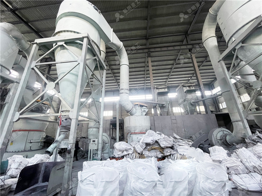
Raymond Mill
Input size:20-30mm
Capacity: 0.8-9.5t/h
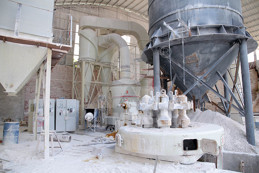
Sand powder vertical mill
Input size:30-55mm
Capacity: 30-900t/h
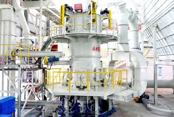
LUM series superfine vertical roller grinding mill
Input size:10-20mm
Capacity: 5-18t/h
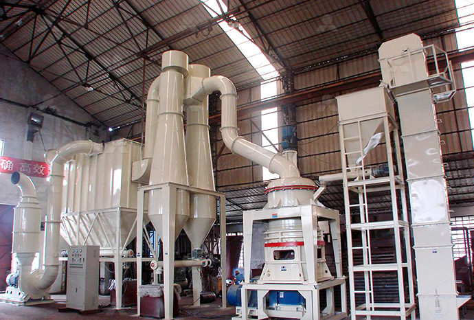
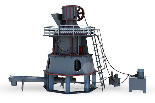
MW Micro Powder Mill
Input size:≤20mm
Capacity: 0.5-12t/h

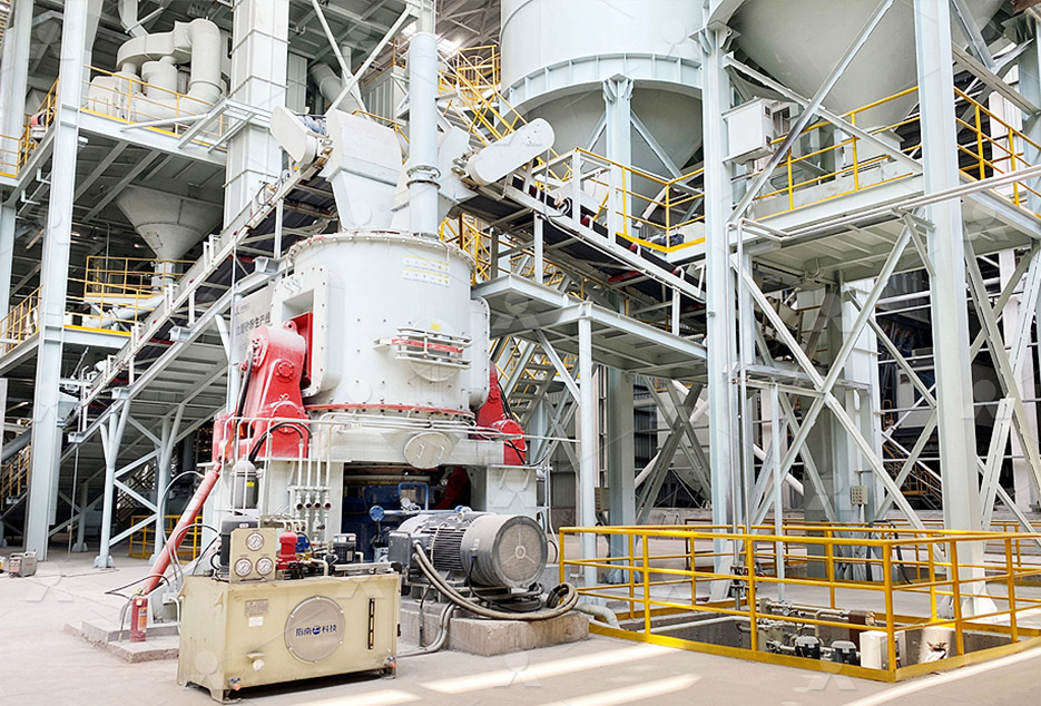
LM Vertical Slag Mill
Input size:38-65mm
Capacity: 7-100t/h

LM Vertical Coal Mill
Input size:≤50mm
Capacity: 5-100t/h
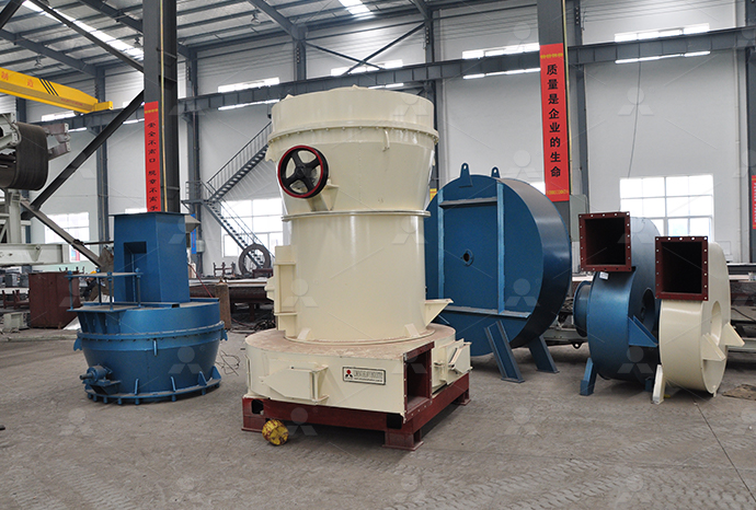
TGM Trapezium Mill
Input size:25-40mm
Capacity: 3-36t/h
MB5X Pendulum Roller Grinding Mill
Input size:25-55mm
Capacity: 4-100t/h
Straight-Through Centrifugal Mill
Input size:30-40mm
Capacity: 15-45t/h
Powder equipment schematic diagram
Powder Metallurgy PDF
2021年6月28日 POWDER METALLURGY •The Characterization of Engineering Powders •Production of Metallic Powders •Conventional Pressing and Sintering •Alternative Pressing Download scientific diagram Schematic diagram of the powdercoating line setup from publication: Production of Thermoplastic Towpregs This work establishes process windows Schematic diagram of the powdercoating line setup experiments were carried out on a powder gun, with a schematic diagram of the powder gun equipment shown in Figure 1 a A GCr15 steel ball with a 3 mm diameter was used as aSchematic diagram of the powder gun Download scientific diagram Schematic diagram of equipment used for powder stream visualization and digital analysis (plan view) from publication: An analytical model of beamSchematic diagram of equipment used for
Processes for Production of HighPurity Metal Powders
2017年8月24日 Processes for producing fine metal powders are listed in Figure 1, while Table I shows the diameters of powders produced through various techniques Atomization is a two 2021年8月27日 1 A hard brittle layer of pure metal which is subsequently milled to obtain powder (eg iron powder) 2 A soft, spongy substance which is loosely adherent and easily Powder metallurgy – basics applications IIT Guwahati2022年6月15日 Powder metallurgybased processes are highly appreciated in the scientific community owing to their versatility in the production of advanced materials that are Chapter 3 Powder Metallurgy Springer2024年1月13日 Schematic diagram of powder metallurgy process Powder preparation methods can be classified into mechanical methods and physicochemical processesPowder Metallurgy SpringerLink

powderprocess Engineering resources for powder
2024年11月3日 PowderProcess is a free online handbook giving explanations, design methods and operational tips on the most common unit operations and equipment found in Download scientific diagram Schematic diagram of the powdercoating line setup The photograph depicted in Figure 2 shows a general overview of the developed powder coating equipment from Schematic diagram of the powdercoating line Download scientific diagram 5: Schematic diagram for a Xray powder diffraction (XRD) experiment Adapted from BRUNDLE ET AL [21] from publication: Magnetic materials with tunable thermal 5: Schematic diagram for a Xray powder 2024年5月20日 A Powder Transfer System (PTS) is a specialised piece of equipment used to move powder materials from one location to another in a safe, efficient, and contained manner Schematic's Powder Transfer Systems (PTS) At Schematic, we pride ourselves on providing cuttingedge technology in Powder Transfer Systems (PTS) for handling hazardous Understanding Powder Transfer Systems Techno Blog Schematic
Schematic diagram of plasma spray system: 1 power supply;
APS equipment is homemade, mainly including the power supply, control cabinet, spray gun, powder feeder, circulating water cooling and gas supply systemsNumerous materials Fig 6 Schematic diagram of Binder Jett equipment for the 3D printing in medical application [22] Powder Roller 3D Printing Technology in the Pharmaceutical and Biomedical Basic diagram of Powder bed fusion equipment2024年1月13日 Schematic diagram of powder metallurgy process medical equipment, petrochemical industry, aerospace, and nuclear industry In order to meet the increasing need of national economy for powder metallurgy, it is necessary to further expand the production of powder metallurgy materials and products, innovate production process, and improve Powder Metallurgy SpringerLink2017年5月15日 Model 250 25Kg ABE Dry Chemical Powder Extinguisher Model 110 / 120 10Kg ABE Dry Chemical Powder Extinguisher Model 150 15Kg ABE Dry Chemical Powder ExtinguisherPARTS LIST AND SCHEMATIC DIAGRAM FIRE
Schematic diagrams of the laser powder bed melting
LPBF process and gas circulating system is schematically shown in Figure 2 [32] Figure 2 a shows LPBF process equipment, which mainly consists of a laser, scanning mirror, fθ lens, protecting 2019年8月29日 8 The powder coating equipment must switch on only after the powder booth is in operation If the booth breaks down, then the powder coating equipment must switch off 9 The grounding of all conductive parts is to be checked at least once a week 10 When cleaning the powder gun and when replacing nozzles the control unit must be switched offEASY 1FE / EASY 2FE Powder Coating EquipmentDownload scientific diagram Schematic of powder bed fusion equipment [34]; with permission from Elsevier from publication: Artificial Neural Network Algorithms for 3D Printing Additive Figure 5 Schematic of powder bed fusion equipment [34]; Download scientific diagram Schematic diagram of the powdercoating line setup from publication: Production of Thermoplastic Matrix Towpregs for Highly Demanding and CostEffective Commercial Schematic diagram of the powdercoating line
Powder delivery system schematic Download
Download scientific diagram Powder delivery system schematic from publication: Variable Powder Flow Rate Control in Laser Metal Deposition Processes This paper proposes a novel technique In addition to including our Drum Containment Systems and Patented Online Sampling Systems, Schematic Engineering offer the latest technology in Powder Transfer Systems (PTS's) for the handling of hazardous powders in safe and Powder Transfer Systems (PTS) ProductsDownload scientific diagram Configurations of ALD reactors for powder fabrication: (a), schematic of the fluidized bed ALD reactor The flexibility of the dosing zone a) allows for the Configurations of ALD reactors for powder fabrication: (a), schematic Download scientific diagram Schematic diagram of equipment used for powder temperature measurement from publication: An analytical model of beam attenuation and powder heating during coaxial Schematic diagram of equipment used for powder
.jpg)
Schematic diagram of equipment used for powder stream
Download scientific diagram Schematic diagram of equipment used for powder stream visualization and digital analysis (plan view) from publication: An analytical model of beam attenuation and Download scientific diagram Schematic diagram of (a) BNNT synthesis equipment and b powder module; c Obtained BNNT fiber right after the reaction; d 10 cm long BNNT fiber; e SEM image of the Schematic diagram of (a) BNNT synthesis equipment and b powder 2016年12月26日 The Powder Recovery Booth The equipment that decides the economical viability of your powder coating paintshop is the powder recovery booth The economies of your paintshop depend on the genuine recovery of oversprayed powder for reuse If you an enduser or using only a few colors (maybe 1 to 3), you want to closely study the possibility of The Powder Coating Plant Process Redline Industries LtdSchematic diagram of the Direct Energy Deposition process The powder particles flow through the nozzle (blue) and it is melted by the focused laser (red) as it is being deposited to create a part Schematic diagram of the Direct Energy Deposition process The powder
.jpg)
Schematic diagram of laser powder bed fusion process
Download scientific diagram Schematic diagram of laser powder bed fusion process followed by thermomechanical postprocessing from publication: Ultrasonic surface postprocessing of hot 2019年8月29日 INSTALLATION OF THE POWDER COATING EQUIPMENT The Manual Powder equipment is preassembled in the factory Only certain cables and hoses must be connected by the customer (See also separate assembly instructions) 1 Connect the hose for the compressed air supply from compressed air circuit directly to the main air connection 11 EASY 1C Powder Coating Equipment gemaoptiflex2024年5月22日 reflection exist for powder samples, and the ThetaTheta BraggBrentano is the most common one In contrast to this BraggBrentano geometry it is possible to obtain a realtime full pattern without moving parts by using a Thermo Scientific PSD (Position Sensitive Detector) Schematics of both these geometries are shown here An XRD patternQuick guide Powder Xray Diffraction (XRD) Thermo 2024年4月5日 A comprehensive laser powder bed fusion normalised process diagram constructed from dimensionless numbers the DOE procedure begins with a screening design encompassing the widest range of equipment capabilities, followed by further refinements using RSM Considering a schematic illustration of the LPBF process in Fig 1, Predictive process diagram for parameters selection in laser powder
Configurations of ALD reactors for powder fabrication: (a), schematic
Download scientific diagram Configurations of ALD reactors for powder fabrication: (a), schematic of the fluidized bed ALD reactor The flexibility of the dosing zone a) allows for the 2022年6月14日 What is a Powder Diffraction Pattern? a powder diffractogram is the result of a convolution of a) the diffraction capability of the sample (F hkl) and b) a complex system function The observed intensity y oi at the data point i is the result of y oi = ∑of intensity of "neighbouring" Bragg peaks + background The calculated intensity yIntroduction to Powder XRay Diffraction Institute of 2024年1月1日 Granulation is a process that is wellknown and widely used in various industries This is primarily used when bulk material in the form of a fine powder is considered difficult to treat and process [1]The process is designed to convert fine powders into granular materials with controlled physical properties, ie a specific shape (granule size) and a specific bulk densityPowder agglomeration processes of bulk materials – A state Download scientific diagram Schematic diagram of CMTWAAM equipment from publication: Microstructure evolution and mechanical behavior of additively manufacturing of AlSi alloy by cold metal Schematic diagram of CMTWAAM equipment ResearchGate
Schematic diagram of dry powder inhaler formulations and
Download scientific diagram Schematic diagram of dry powder inhaler formulations and dispensing powder mechanisms a Drugonly formulation (drug agglomerates); b Carrierbased formulation 2024年1月15日 Sidebyside comparison of the wiring diagram (drawing), the actual device, and the circuit schematic of the output circuits (MOSFET and Zener diode visible) Image used courtesy of the author Many devices exist in both diagrams and schematics Both will contain indicators, relays, power supply connections, transformers, fuses, and othersElectrical Drawings, Schematics, and Wiring Diagrams: How The development of 3D printing methods and of printing materials enabled users to print 3D parts on demand, which is crucial in fast prototyping of new equipment or resolving problems with Schematic diagram of powder yield locus obtained from the Download scientific diagram Schematic diagram of the powdercoating line setup The photograph depicted in Figure 2 shows a general overview of the developed powder coating equipment from Schematic diagram of the powdercoating line
5: Schematic diagram for a Xray powder
Download scientific diagram 5: Schematic diagram for a Xray powder diffraction (XRD) experiment Adapted from BRUNDLE ET AL [21] from publication: Magnetic materials with tunable thermal 2024年5月20日 A Powder Transfer System (PTS) is a specialised piece of equipment used to move powder materials from one location to another in a safe, efficient, and contained manner Schematic's Powder Transfer Systems (PTS) At Schematic, we pride ourselves on providing cuttingedge technology in Powder Transfer Systems (PTS) for handling hazardous Understanding Powder Transfer Systems Techno Blog SchematicAPS equipment is homemade, mainly including the power supply, control cabinet, spray gun, powder feeder, circulating water cooling and gas supply systemsSchematic diagram of plasma spray system: 1 power supply; Numerous materials Fig 6 Schematic diagram of Binder Jett equipment for the 3D printing in medical application [22] Powder Roller 3D Printing Technology in the Pharmaceutical and Biomedical Basic diagram of Powder bed fusion equipment
Powder Metallurgy SpringerLink
2024年1月13日 Schematic diagram of powder metallurgy process medical equipment, petrochemical industry, aerospace, and nuclear industry In order to meet the increasing need of national economy for powder metallurgy, it is necessary to further expand the production of powder metallurgy materials and products, innovate production process, and improve 2017年5月15日 Model 250 25Kg ABE Dry Chemical Powder Extinguisher Model 110 / 120 10Kg ABE Dry Chemical Powder Extinguisher Model 150 15Kg ABE Dry Chemical Powder ExtinguisherPARTS LIST AND SCHEMATIC DIAGRAM FIRE LPBF process and gas circulating system is schematically shown in Figure 2 [32] Figure 2 a shows LPBF process equipment, which mainly consists of a laser, scanning mirror, fθ lens, protecting Schematic diagrams of the laser powder bed melting 2019年8月29日 8 The powder coating equipment must switch on only after the powder booth is in operation If the booth breaks down, then the powder coating equipment must switch off 9 The grounding of all conductive parts is to be checked at least once a week 10 When cleaning the powder gun and when replacing nozzles the control unit must be switched offEASY 1FE / EASY 2FE Powder Coating Equipment
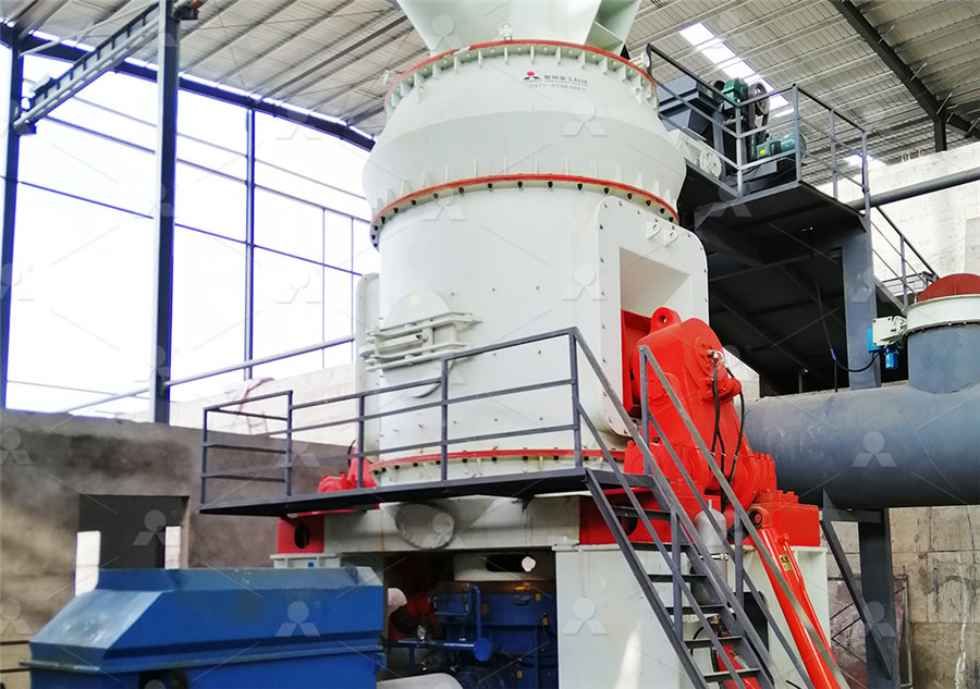
Figure 5 Schematic of powder bed fusion equipment [34];
Download scientific diagram Schematic of powder bed fusion equipment [34]; with permission from Elsevier from publication: Artificial Neural Network Algorithms for 3D Printing Additive