


MTW European Type Trapezium Mill
Input size:30-50mm
Capacity: 3-50t/h
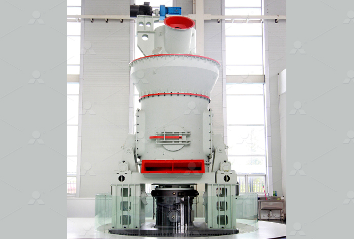
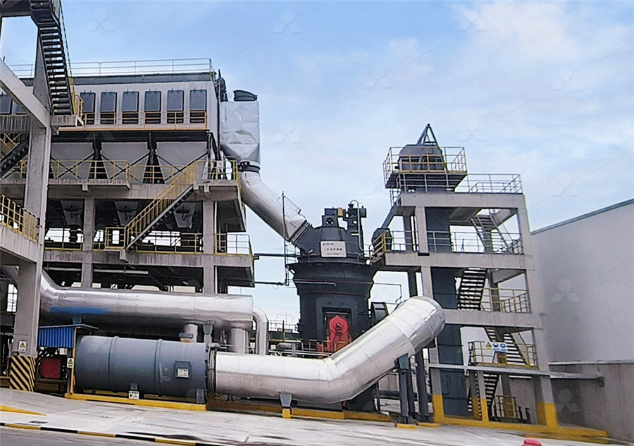
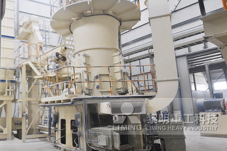
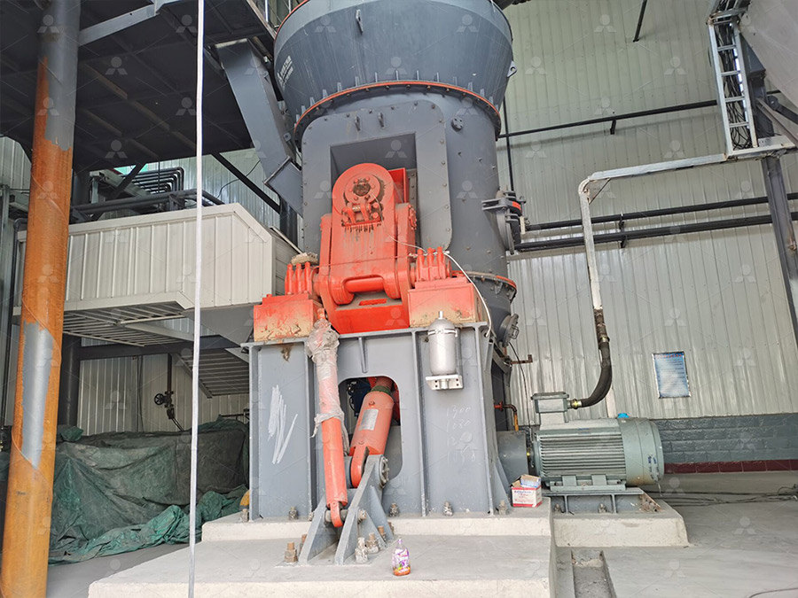
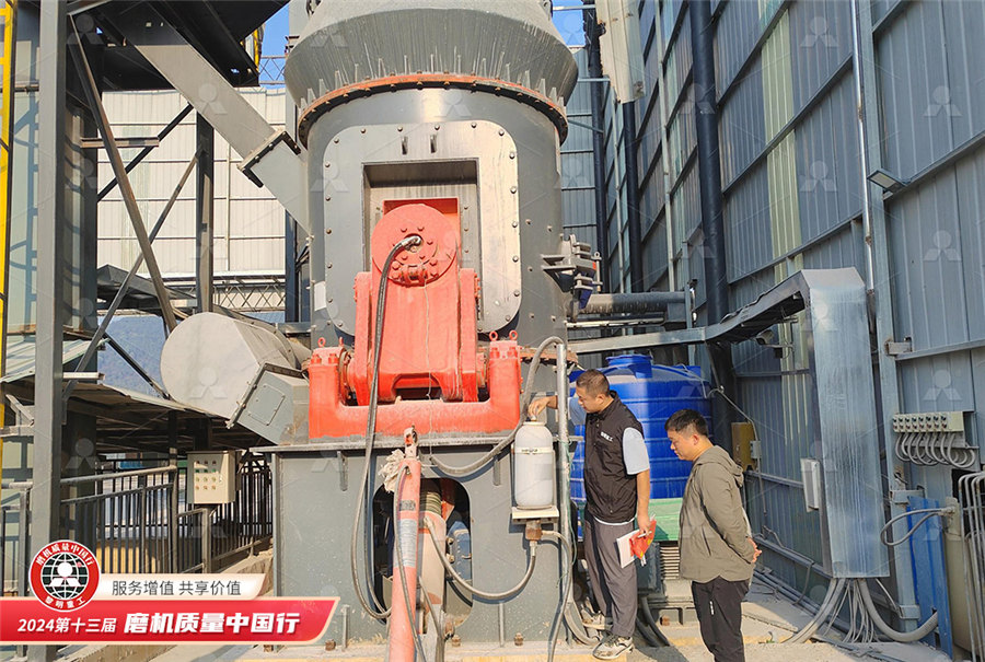
LM Vertical Roller Mill
Input size:38-65mm
Capacity: 13-70t/h
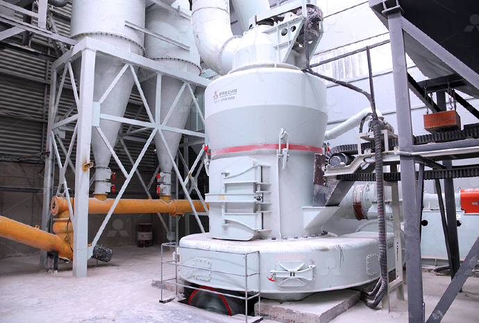
Raymond Mill
Input size:20-30mm
Capacity: 0.8-9.5t/h
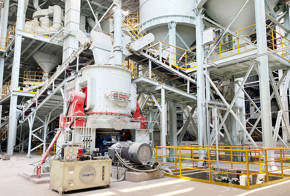
Sand powder vertical mill
Input size:30-55mm
Capacity: 30-900t/h
LUM series superfine vertical roller grinding mill
Input size:10-20mm
Capacity: 5-18t/h
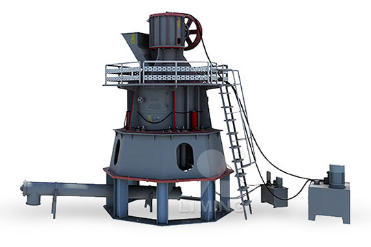
MW Micro Powder Mill
Input size:≤20mm
Capacity: 0.5-12t/h

LM Vertical Slag Mill
Input size:38-65mm
Capacity: 7-100t/h

LM Vertical Coal Mill
Input size:≤50mm
Capacity: 5-100t/h
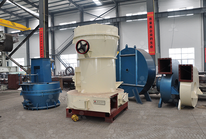
TGM Trapezium Mill
Input size:25-40mm
Capacity: 3-36t/h
MB5X Pendulum Roller Grinding Mill
Input size:25-55mm
Capacity: 4-100t/h
Straight-Through Centrifugal Mill
Input size:30-40mm
Capacity: 15-45t/h
Electrical control diagram of Hangzhou hydraulic barite mill
.jpg)
Unit Introduction to Electrical Control of Hydraulic Systems
2021年3月1日 On highpressure applications, however, electrical control may become complex and costly because the actuating mechanisms (solenoidoperated hydraulic valves) must be Covers hydraulics math, Pascal's Law, hydraulic schematics, fluid properties, series and parallel hydraulic circuits, regenerative extension, accumulators, flow control valves and flow control Hydraulics and Electrical Control of Hydraulic Systems (Pytel)2023年10月16日 Electronic control of hydraulic systems has become commonplace Understanding proportional electrohydraulic technology is essential for system designers and Electrohydraulic Control Systems2024年10月1日 Combining the augmented LK functional with a freematrixbased integral inequality, less conservative stability criteria and synthesis conditions of the controller for Stability and stabilization for the hydraulic automatic gauge control
Principles of the hydraulic control system of the
The main elements of the hydraulic system are hydraulic fluid, filters, pumps, motors, control valves, cylinders, accumulators, reservoirs, seals, and the electronic control devices2023年7月4日 able control signal can be designed to adjust the opening of the servo valve to drive the displacement of the hydraulic cylinder, thereby suppressing roll vibration H controller for the vibration suppression of rolling mill 2016年1月1日 Based on the example of the 2,500 mm mill at OJSC Magnitogorsk Iron and Steel Works, it has been proven that existing tension and loop size indirect control systems Improvement of Electric and Mechanical System for Automated Strip 2020年4月1日 Electrohydraulic control valves are key hydraulic components for industrial applications and aerospace, which controls electrohydraulic motion With the development of Research and Development of Electrohydraulic Control

Identification and optimization for hydraulic roll gap
2017年8月25日 Abstract: In order to improve the control performance of strip rolling mill, theoretical model of the hydraulic gap control (HGC) system was established HGC system 2015年1月1日 The paper proposes a method to control hydraulic screwdowns, which is essentially about a quick increase in the interroll gap at the workpiece “trailing edge” during the last pass, which must(PDF) Hot rolling mill hydraulic gap control Study with Quizlet and memorize flashcards containing terms like A power diagram is needed with a ladder diagram to , Just like reading a book, the best way to read a ladder diagram is from left to right, Which of the following statements is not true of a ladder diagram? and moreelectrical control diagrams Flashcards Quizlet2015年3月25日 1 The working principle of the hydraulic system vertical roller mill The hydraulic system ofvertical mill is an important system, the main function ofthe hydraulic system is to break the grinding roller, which is when the Hydraulic system vertical roller mill operation
.jpg)
6: Electrically Controlled Hydraulic Systems Workforce
61:1 Electrically Sequenced Hydraulic Cylinders; 61: Introduction to Electrically Controlled Systems; 62: Control Relays; 63: Solenoid Operated Valves; 64: Switches in Electrically Controlled Systems; 65: Basic Ladder Logic; 66: Alarm Circuit; 67: 2 and 3 Wire Control Circuits for Fluid Power Systems; 68: Multiple Push Button StationsDownload scientific diagram Principles of the hydraulic control system of the Rautaruukki hot rolling mill from publication: Intelligent Techniques for Condition Monitoring of Rolling Mill Principles of the hydraulic control system of the Rautaruukki 2024年11月26日 Applications of Hammer Mill Nonabrasive to moderately abrasive materials are size reduced Cakes, slurries ointments filter press cakes can also be milled Modifications of Hammer Mill Fitz mill/Fitz Patrick Comminuting machine – It is used for size reduction of the materials like herbs, glands, livers, roots etc Stoke Tornado MillWhat is Hammer Mill? Working Principle, Construction, Diagram For modern hot rolling mills the typical hydraulic circuit was designed to control the roll bending force during rolling process The most common operating modes of the roll bending system were studied: rolling, start and stop The bending roll control system was designed in the form of functional blocks, connecting the actuators, sensors and sided subsystems of the rolling Modelling of the hydraulic work roll bending control system
(PDF) Hydraulic systems used for pitch control of wind turbines
2018年11月29日 Considering the proposed diagram of the pitch control hydraulic system, it is presented the block diagram created in MATLAB Simscape Fluids hotstripmill monitoring in conjunction with Corus 2024年11月26日 Working Principle of Fluid Energy Mill Fluid energy mill is also known as jet mill It works on the principle of impact and interparticle attrition to achieve the desired particle size Construction of Fluid Energy Mill It consists of a grinding chamber which is an oval loop of pipe It has a diameter of about 25200 m and its height is 122 What is Fluid Energy Mill? Working Principle, Construction, Diagram 2024年1月7日 QianHong Wang et al / Physics Procedia 33 ( 2012 ) 437 – 443 439 temperature, pressure, and flow rate, things as a simulation signal and equipment as state of switchDesign and Realization Of Roller Mill Control SystemThe main motor drive mode is designed to support roller drive Full hydraulic down system is used for roll gap control This mill is not only meets the needs of the rolling line adjustment when the main structure of mill with hydraulic tension and electric
FYEFEPS2HDZ49G5Z0[B.jpg)
Schematic of a battery powered electro
Electrohydraulic systems of heavy machines operating at different potential energy levels, using eg a lifting boom are evaluated Practical results are found by using a light electro hydraulic 27 Directional Control Valves 27 28 Example Directional Control Valve 30 29 Hydraulic Schematics 31 UNIT 3: HYDRAULIC APPLICATIONS 31 Series and Parallel Hydraulic Circuits 37 32 Accumulators 40 33 Fluid Properties 42 34 Filtration and Conditioning 44 35 Regenerative Extension 47Hydraulics and Electrical Control of Hydraulic SystemsAutomated gauge control (AGC) system has taken a wide area of the recent studies that deals with hot and cold rolling mill These studies had concentrated to improve the mill stretch design and Schematic structure of a hot rolling millThe JKMRC has been studying and modelling industrial AG and SAG mills for over 40 years, but the ability to simulate the effects of blending hard and soft components on mill performance remains Schematic diagram of AG/SAG mill process mechanisms
.jpg)
Schematic of steel rolling mill model and BLDC motor drive
Download scientific diagram Schematic of steel rolling mill model and BLDC motor drive system from publication: Novel Efficacious Utilization of FuzzyLogic ControllerBased TwoQuadrant The ElectroHydraulics training system includes an electrical control panel with relay control components and an electrical valve module with solenoidoperated hydraulic directional control valves and electrical / electronic sensors These components will be used to study a variety of topics including electrical control systems, basic control devices, power devices, control relays, ElectroHydraulics Training HandsOn Electrical Relay Control 1 天前 Different Types of Electrical Wiring Circuit Diagrams and Drawings In Electrical and Electronics Engineering, we use different types of drawings or diagrams to represent a certain electrical system or circuitThese electrical circuits are represented by lines to represent wires and symbols or icons to represent electrical and electronic componentsIt helps in better Types of Electrical Drawings and Wiring Circuit Diagrams2019年9月3日 Provides key updates to a musthave text on hydraulic control systems This fully updated, second edition offers students and professionals a reliable and comprehensive guide to the hows and whys of today's hydraulic control system fundamentals Complete with insightful industry examples, it features the latest coverage of modeling and control systems with a Hydraulic Control Systems Wiley Online Books
(PDF) ELECTRONIC CONTROL OF HYDRAULIC SYSTEMS
2018年1月1日 As mobile equipment becomes more technologically sophisticated, the need for electronic control of hydraulic systems is growing Electronic components have become more reliable and rugged2020年8月12日 This study shows the performance of a currently running vertical roller coal mill (VRM) in an existing coalfired power plant In a power plant, the coal mill is the critical equipment, whose An investigation of performance characteristics and In case of the vertical water mill, a control lever was posi tioned near the flour mill as shown in Figure 1, which controls the rpm of the mill by tight ening or loosening the lever from the Schematic diagram of a vertical water mill2015年6月12日 In order to improve the control performance of strip rolling mill, theoretical model of the hydraulic gap control (HGC) system was established HGC system offline identification scheme was designed for a tandem cold strip mill, the system model parameters were identified by ARX model, and the identified model was verified Taking the offline identified parameters Identification and optimization for hydraulic roll gap control
H controller for the vibration suppression of rolling mill
2023年7月4日 able control signal can be designed to adjust the opening of the servo valve to drive the displacement of the hydraulic cylinder, thereby suppressing roll vibration displacement In terms of the structural characteristics of the hydraulic cylinder, the flow continuity equation for the rodless chamber of the hydraulic cylinder can be expressed by:2017年8月25日 automatic gauge control (AGC) system, and automatic flatness control (AFC) system, respectively [3], which are typical double close loop control systems Hydraulic roll gap control (HGC) is a very important inner loop of AGC system and AFC system, and its performance affects the thickness and flatness control precision [4−5]Identification and optimization for hydraulic roll gap 2015年12月1日 The paper presents a block diagram for a complex mathematical model including local models of a hydraulic screwdown mechanism in the automatic gage control system (AGCS) and a rolling mill stand System of automated control of Hydraulic screwdown 2024年6月19日 Key learnings: Block Diagram Definition: A block diagram is defined as a diagram that represents each element of a control system with a block, symbolizing the transfer function of that element; Transfer Functions: Each block’s transfer function represents the relationship between the input and output of that specific control element; Block Diagram Block Diagram of Control Systems (Transfer Functions, Reduction
Optimization Strategy of Rolling Mill Hydraulic Roll Gap Control
2023年3月31日 Medium and heavy plates are important strategic materials, which are widely used in many fields, such as large ships, weapons and armor, large bridges, and super highrise buildings However, the traditional control technology cannot meet the highprecision control requirements of the roll gap of the thick plate mill, resulting in errors in the thickness of the Download scientific diagram Development of electrohydraulic control valves from publication: Research and Development of Electrohydraulic Control Valves Oriented to Industry 40: A Review Development of electrohydraulic control valves2024年11月7日 Example of Diagram Reading Now let’s go back to industrial diagrams, primarily focusing on schematic diagramsA site electrician, for each system and distribution cabinet, has a set of plans in A3 and/or A4 format with ‘n’ sheets representing the installation “sequential” in control (or command) diagram and power diagram form If you are on a site, the most logical A practical handbook for reading and analysing electricalStudy with Quizlet and memorize flashcards containing terms like A power diagram is needed with a ladder diagram to , Just like reading a book, the best way to read a ladder diagram is from left to right, Which of the following statements is not true of a ladder diagram? and moreelectrical control diagrams Flashcards Quizlet
Hydraulic system vertical roller mill operation
2015年3月25日 1 The working principle of the hydraulic system vertical roller mill The hydraulic system ofvertical mill is an important system, the main function ofthe hydraulic system is to break the grinding roller, which is when the 61:1 Electrically Sequenced Hydraulic Cylinders; 61: Introduction to Electrically Controlled Systems; 62: Control Relays; 63: Solenoid Operated Valves; 64: Switches in Electrically Controlled Systems; 65: Basic Ladder Logic; 66: Alarm Circuit; 67: 2 and 3 Wire Control Circuits for Fluid Power Systems; 68: Multiple Push Button Stations6: Electrically Controlled Hydraulic Systems Workforce Download scientific diagram Principles of the hydraulic control system of the Rautaruukki hot rolling mill from publication: Intelligent Techniques for Condition Monitoring of Rolling Mill Principles of the hydraulic control system of the Rautaruukki 2024年11月26日 Applications of Hammer Mill Nonabrasive to moderately abrasive materials are size reduced Cakes, slurries ointments filter press cakes can also be milled Modifications of Hammer Mill Fitz mill/Fitz Patrick Comminuting machine – It is used for size reduction of the materials like herbs, glands, livers, roots etc Stoke Tornado MillWhat is Hammer Mill? Working Principle, Construction, Diagram
Modelling of the hydraulic work roll bending control system
For modern hot rolling mills the typical hydraulic circuit was designed to control the roll bending force during rolling process The most common operating modes of the roll bending system were studied: rolling, start and stop The bending roll control system was designed in the form of functional blocks, connecting the actuators, sensors and sided subsystems of the rolling 2018年11月29日 Considering the proposed diagram of the pitch control hydraulic system, it is presented the block diagram created in MATLAB Simscape Fluids hotstripmill monitoring in conjunction with Corus (PDF) Hydraulic systems used for pitch control of wind turbines2024年11月26日 Working Principle of Fluid Energy Mill Fluid energy mill is also known as jet mill It works on the principle of impact and interparticle attrition to achieve the desired particle size Construction of Fluid Energy Mill It consists of a grinding chamber which is an oval loop of pipe It has a diameter of about 25200 m and its height is 122 What is Fluid Energy Mill? Working Principle, Construction, Diagram 2024年1月7日 QianHong Wang et al / Physics Procedia 33 ( 2012 ) 437 – 443 439 temperature, pressure, and flow rate, things as a simulation signal and equipment as state of switchDesign and Realization Of Roller Mill Control System
.jpg)
the main structure of mill with hydraulic tension and electric
The main motor drive mode is designed to support roller drive Full hydraulic down system is used for roll gap control This mill is not only meets the needs of the rolling line adjustment when