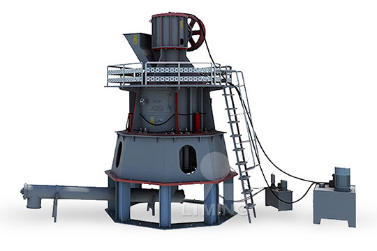
Schematic diagram of the working principle of a threestage rocket

List of Illustrations AIAA Aerospace Research Central
33 A2 Stage EngineSystem Schematic Diagram BoosterStage Rocket Engine System 625 Effect of TurbineInlet Temperature on WorkingFluid Available Energy 173 626 Effect detonating rope winds around the inner surface (in a fixed position) of the thin cover of the interstage sector During separation, electricity is switched on to ignite the detonating rope; the SEPARATION BETWEEN STAGES OF MULTISTAGE CARRIER 2024年5月16日 A rocket propulsion system is primarily designed to produce thrust, which propels a rocket through the air and space What fundamental principle governs rocket Rocket Propulsion Types, Principles, Diagram, Elements Vajiram 2021年5月13日 In the Principia, Newton stated three important scientific principles that govern the motion of all objects, whether on Earth or in space Knowing these principles, now called Rocket Principles NASA

Design and Implementation of a Threestage Amplifier
2018年11月25日 This report presents a detailed procedure and methodology involved in the design and implementation of a threestage amplifier with lower cutoff frequency of about 400 What Does a Rocket Engineer/Scientist Need to Know ? • Rocket propulsion is a very interdisciplinary field • Some of the important fields are – Fluid dynamics/gas dynamics – Lecture 1 Introduction to Rocket Propulsion Stanford University2023年11月20日 On this page, we show a schematic of a solid rocket engine Solid rocket engines are used on airtoair and airtoground missiles, on model rockets, and as boosters Solid Rocket Engine Glenn Research Center NASAHow Rockets Work W hether flying a small model rocket or launching a giant cargo rocket to Mars, the principles of how rockets work are exactly the same Understanding and applying Rockets Guide How Rockets Work NASA
.jpg)
Layout, schematics, and working principle of the
Download scientific diagram Layout, schematics, and working principle of the passive cooling device (A) Schematic of the working principle of a generic salinitydriven cooler: The salinity 2021年8月16日 Working Principle of a Three Point Starter The threepoint starter is mainly used for starting shunt and compound motorsSchematic Diagram of Three Point StarterThe circuit diagram of the threepoint starter is shown in the figure It is called threepoint starter because it has three terminals viz L, Z and A It consists of a graded startiWorking Principle of a ThreePoint Starter Online Tutorials Phase Locked Loop Working Principle: changes of the input signal Thus, a Phase Locked Loop Working goes through three states : free running, capture and phase lock Related posts: Important Definition of Phase Locked Loop; Phase Locked Loop Working Principle PLL block How It Works, Internal Schematic and Block Diagram Let’s take a closer look what’s inside the 555 Timer and explain how it works in each of the three modes Here’s the internal schematics of 555 Timer which consists of 25 transistors, 2 diodes and 15 resistors555 Timer IC – Working Principle, Block Diagram, Circuit Schematics
.jpg)
Reciprocating Compressor – Diagram , Parts , Working,
Schematic diagram of the singlecylinder compressor is shown in Figure Fig shows various parts of threestage (V type) reciprocating air compressor with the receiver Application Reciprocating Pump – Construction and Working animation Roots Blower – Parts , Working , Diagram, Efficiency, Advantages Centrifugal Compressor – Diagam Download scientific diagram Schematic diagram of working principle from publication: Colorless movement of focal spot with arbitrary velocity based on mirrors with special shape Focal spot Schematic diagram of working principle ResearchGateWorking Principle of Centrifugal Compressor : Air is sucked into the impeller eye and whirled outwards at high speed by the impeller disk At any point in the flow of air through the impeller the centripetal acceleration is obtained by a pressure head so that the static pressure of the air increases from the eye to the tip of the impellerCentrifugal Compressor Diagam, Parts, Working, Efficiency, 2022年3月11日 Figure 1 shows a twostage CW multiplier Each stage consists of two capacitors and two diodes In this case stage one consists of capacitors C1 and C2, and diodes D1 and D2 The second stage consists of C3, C4, D3 and D4 The input to the circuit is an AC voltage which can be sinusoidal or in the form of a square waveCockcroftWalton Voltage Multiplier Circuit Cellar
Impulse Voltage Generator / Marx Generator – Circuit Diagram, Working
2019年12月9日 In electronics, surges are a very critical thing and it is a nightmare for every circuit designer These surges are commonly referred to as impulse which can be defined as a high voltage, typically in a few kV which exists for a short duration of timeThe characteristics of an impulse voltage can be noticed with a High or Low fall time followed by a very high rise time 2024年5月16日 Principle and Working of Rocket Propulsion Newton's third law of motion, which states that every action has an equal and opposite reaction, is one of the principles underlying rocket propulsion When a rocket ejects propellant at high speed from the back, it produces an equal and opposite force that propels the rocket forwardRocket Propulsion Types, Principles, Diagram, Elements2023年9月25日 A Vapour Absorption Refrigeration System (VARS) is a thermally driven cooling system that utilises the absorption and desorption of a refrigerant by an absorbent to provide cooling It is a unique and Vapour Absorption Refrigeration System Diagram, Download scientific diagram Schematic circuit of a basic 4stage CockcroftWalton voltage multiplier from publication: A Comparative Study of Symmetrical CockcroftWalton Voltage Multipliers Schematic circuit of a basic 4stage CockcroftWalton voltage
.jpg)
Torque Converter Working Principle, Diagram,
2023年7月31日 Torque Converter: Learn Working Principle, Diagram, Functions, Components, Types Last Updated on Jul 31, 2023 Download as PDF 420 hp at 2200 rpm, and 580 hp at 2200 rpm A threestage converter 2024年10月4日 Schematic diagrams only depict the significant components of a system, though some details in the diagram may also be exaggerated or introduced to facilitate the understanding of the system Schematic diagrams do not include details that are not necessary for comprehending the information that the diagram was intended to conveyWhat Is a Schematic Diagram? ThoughtCoDownload scientific diagram Schematic diagram of a fuel cell working principle from publication: Future of Electric and Hydrogen Cars and Trucks: An Overview The negative consequences of Schematic diagram of a fuel cell working principle Download Download scientific diagram Schematic of the capillary viscometer's working principle Three segments of capillary tubing of known radius, r, were connected with a Yconnector Sample fluid in Schematic of the capillary viscometer's working principle Three
.jpg)
Gas Turbine Working Principle, Main Components, and Types:
Read Also: Different types of Jet Engines 3) Turbofan Engine The jet engine that generates power by using a ducted fan is commonly referred to as a turbofan engineThe word “turbofan” is a combination of “turbine” and “fan“: the word turbine represents a gas turbine that gets mechanical power from the combustion chamber, and the fan represents the ducted fan, which Steam Turbine Working Principle A steam turbine works on the basic principle of the Rankine cycle The basic principle of a steam turbine involves the expansion of highpressure steam through a series of stages, where it passes over sets of stationary and rotating blades Image source: schoolworkhelperSteam Turbine: Working, Types, Components, and ApplicationsDownload scientific diagram Schematic diagram of the working principle from publication: Experimental Investigation on the Performance of a Novel Solar air Heater Based on Flat Microheat Pipe Schematic diagram of the working principle ResearchGateDownload scientific diagram Schematic of the lithium ion battery working principle 31 from publication: The combustion behavior of large scale lithium titanate battery Safety problem is Schematic of the lithium ion battery working principle 31
Scanning Electron Microscope (SEM) Diagram,
2022年10月6日 Working principle and Diagram of SEM The three types of electron sources that are used to generate a focused beam of electrons include : 1 The sample stage can be moved up and down as per the requirement 2020年10月15日 A switchedmode power supply or in short SMPS is a power supply circuit that converts mains power using switching devices that are turned on and off at high frequencies, and storage components such as inductors or SwitchedMode Power Supply (SMPS) Circuit 2024年4月17日 An electrical motor is an electromechanical device that converts electrical energy into mechanical energy In the case of threephase AC (Alternating Current) operation, the most widely used motor is a 3 phase Three Phase Induction Motor Definition Working Working principle: The main working principle is associated with centrifugal force: Mainly reciprocating action or rotary or diaphragm action Creation of Suction lift: This pump is not able to create a vacuum as well as a suction lift This pump creates a What is a Centrifugal Pump? Working Principle, Parts, Types, Diagrams
(PDF) Principles of Multistage Rocket Vehicle and Concepts of
2022年12月27日 A unique hybrid rocket engine is considered, employed in different numbers in each stage of the threestage launcher: six, three, and one, respectively, in the first, second, and third stage2024年4月18日 Key learnings: Solar Cell Definition: A solar cell (also known as a photovoltaic cell) is an electrical device that transforms light energy directly into electrical energy using the photovoltaic effect; Working Principle: The working of solar cells involves light photons creating electronhole pairs at the pn junction, generating a voltage capable of driving a current across Solar Cell: Working Principle Construction (Diagrams Included)Download scientific diagram a Schematic diagram of the working principle of a solar cell, b energy band diagram of CIGSebased solar cell from publication: Perspectives of chalcopyritebased a Schematic diagram of the working principle of a solar cell, b When the temperature is high, the electrolyte material acts as a sieve and the hydrogen ions migrates through the material An electrical load is connected between the anode and the cathode The chemical reaction in the cathode, the energy representing the enthalpy of combustion of fuel is released and a part of it is available for conversion into electrical energyFuel Cell Working Principle and Schematic Diagram: EEEGUIDE
Schematic diagram of three stage CMOS ring oscillator The schematic
Download scientific diagram Schematic diagram of three stage CMOS ring oscillator The schematic diagram of three stage conventional CMOS ring oscillator is shown in Fig 2 It works at the 2021年5月13日 Rocket Principles A rocket in its simplest form is a chamber enclosing a gas under pressure A small opening at one end of the chamber allows the gas to escape, and in doing so provides a thrust that propels the rocket in the Rocket Principles NASAWorking principle Hydroelectric power plant (Hydel plant) utilizes the potential energy of water stored in a dam built across the river The potential energy of the stored water is converted into kinetic energy by first passing it through the Hydroelectric power plant – Diagram , Working , 2024年3月28日 Parts of a Compound Microscope The structural and optical components of the compound microscope are as follows: Head/ Body Tube: It forms the top section of the microscope which holds prisms and eyepiece Compound Microscope: Principle, Parts, Uses, Diagram
.jpg)
Reciprocating Pumps: Parts, Diagram, Types and Working Principle
This is similar in principle to the double acting pump (ii) The Triple Cylinder or the Three Throw Pump: This pump consists of three single acting cylinders Each cylinder is provided with a suction and delivery pipe with their valves and a separate piston or plunger The three plungers are driven simultaneously by cranks which are set at 120°Definition: Phaselocked loops are the circuits used to maintain synchronization between input and output frequency of oscillator circuits by comparing the difference in phase of the two signalsWith the evolution of IC, it has emerged as the basic building block of electronic circuits Phaselocked loops are abbreviated as PLL and are basically a feedback circuit comprising of What are PhaseLocked Loops (PLL)? Definition, Block Diagram, Working 2018年10月27日 2212 Working Principle Working principle of W filament electron gun is depicted in the schematic diagram shown in Fig 25 Electric current is used to resistively heat the Vshaped filament to the temperature of up to 2500 °C The tip offers the highest resistance to the flow of current and thus becomes the hottest part of the ponents of the SEM SpringerLinkI like the definition of schematic in Wikipedia: “A schematic, or schematic diagram, is a representation of the elements of a system using abstract, graphic symbols rather than realistic pictures A schematic usually omits all details that are not relevant to the information the schematic is intended to convey, and may add unrealistic elements that aid comprehension The Schematic Diagram: A Basic Element of Circuit Design
Ring Oscillator : Layout, Circuit Diagram and Its Applications
The above two diagrams are showing the schematic and output waveforms for 3 stage ring oscillator Here, the PMOS size is double than of the NMOS The NMOS size is 105 and PMOS is 21 ringoscillatorlayout From these values, the time period of 2024年10月21日 Working Principle of Rankine Cycle The study of components in the cycle helps us understand that the cycle operates in a closed loop where the working fluid is reused Let us consider the Rankine cycle Pv and Ts diagrams with the hs diagram to understand the working Fig 2: TemperatureEntropy (Ts) Diagram Fig 3: PressureVolume (Pv) DiagramRankine Cycle: Working Principle, Components, Efficiency, Types 2024年8月5日 Key Features Developmental Stages: Piaget proposed four sequential stages of cognitive development, each marked by distinct thinking patterns, progressing from infancy to adolescence; Constructivist Approach to Learning: Children actively build understanding by exploring their environment as “little scientists,” rather than passively absorbing informationPiaget’s Theory and Stages of Cognitive Development Simply 2024年2月27日 Power Flow Diagram Referring to the power flow diagram, Iron and friction losses = A B Copper Losses = BC As a result, the efficiency of a DC generator may be determined for all three stages: Mechanical efficiency To calculate mechanical efficiency, use the formula: ηmech = B / A = Power developed in armature (Eg Ia) / Mechanical power Construction And Working of a DC Generator GeeksforGeeks


