


MTW European Type Trapezium Mill
Input size:30-50mm
Capacity: 3-50t/h
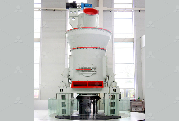
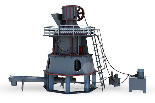
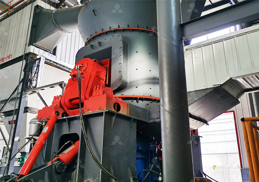
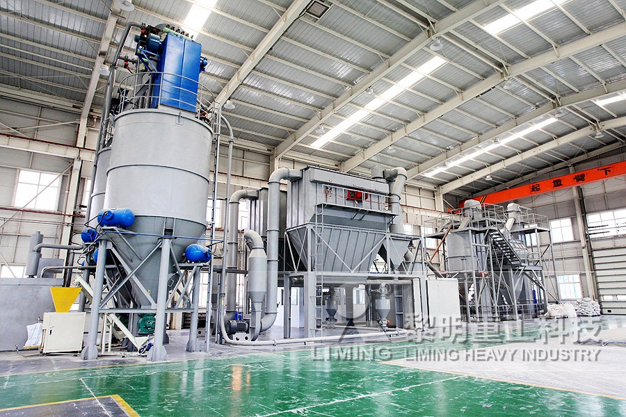
LM Vertical Roller Mill
Input size:38-65mm
Capacity: 13-70t/h
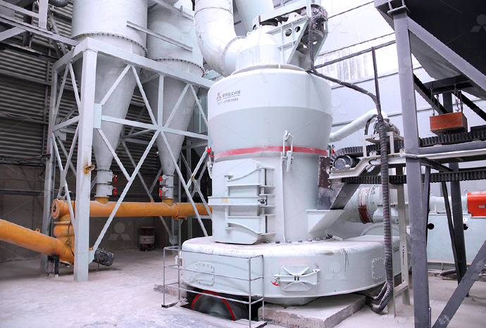
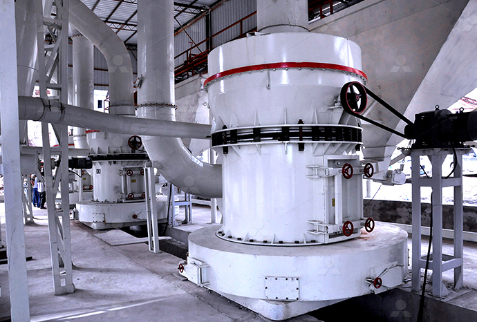
Raymond Mill
Input size:20-30mm
Capacity: 0.8-9.5t/h
Sand powder vertical mill
Input size:30-55mm
Capacity: 30-900t/h
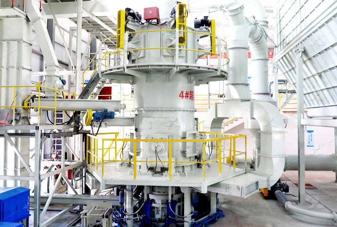
LUM series superfine vertical roller grinding mill
Input size:10-20mm
Capacity: 5-18t/h
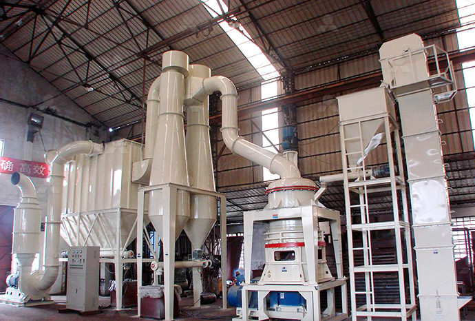
MW Micro Powder Mill
Input size:≤20mm
Capacity: 0.5-12t/h

LM Vertical Slag Mill
Input size:38-65mm
Capacity: 7-100t/h

LM Vertical Coal Mill
Input size:≤50mm
Capacity: 5-100t/h
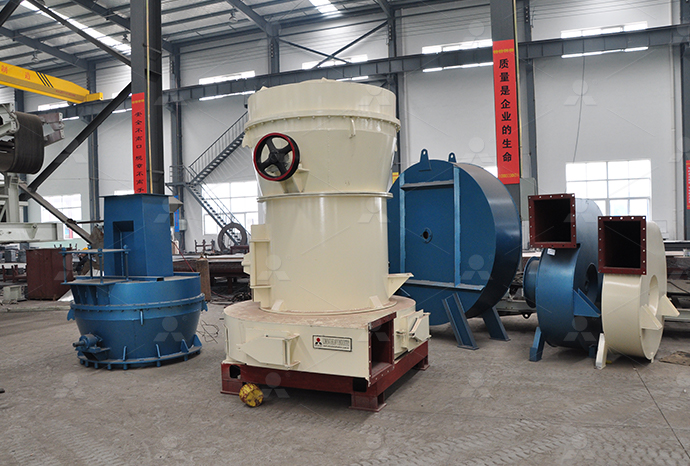
TGM Trapezium Mill
Input size:25-40mm
Capacity: 3-36t/h
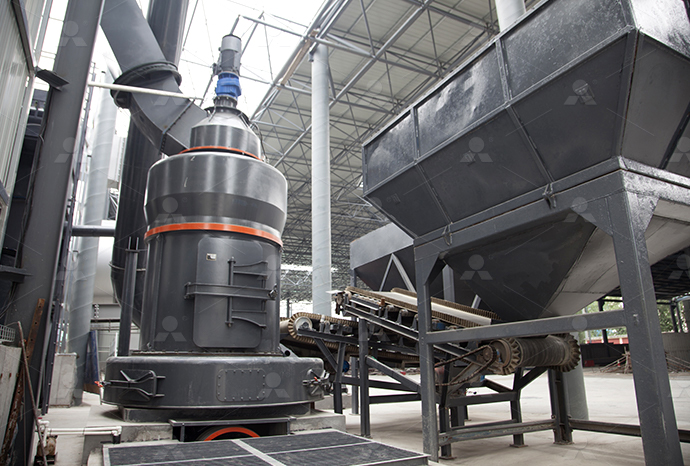
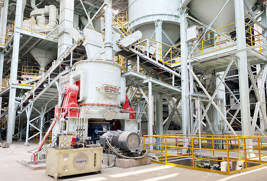
MB5X Pendulum Roller Grinding Mill
Input size:25-55mm
Capacity: 4-100t/h
Straight-Through Centrifugal Mill
Input size:30-40mm
Capacity: 15-45t/h
Hydraulic press system diagram
.jpg)
Hydraulic Press Diagram, Working, Types
The key components of a hydraulic press are the frame, cylinder, reservoir, pump, valve, piston rod, plates, pressure gauge, and hoses It operates based on Pascal's law, using fluid pressure created by a small force on a small piston to Schematic diagrams showing the connection of components in the fluid power sys tem are standardized in ISO 12191 A possible solution for the hydraulic press exam ple is given in 2: Hydraulic circuit diagram for a press ResearchGateDownload scientific diagram Schematic drawing of a hydraulic press system from publication: Turbulent history of fluid mechanics (brief essay) Brief essay about the progress of fluidSchematic drawing of a hydraulic press systemWhat is a Hydraulic Press? A hydraulic press is a machine that utilizes hydraulic pressure to compress materials or objects It typically consists of a large cylinder with a piston inside it The piston is connected to a hydraulic system that Hydraulic Press: Working, Type, Diagram, Application

What is Hydraulic Press? – its Diagram and How it Works
The hydraulic press uses a piston to force hydraulic fluid into a larger cylinder, increasing pressure and force This fluid exchange between the pistons drives the anvil downward onto a 2019年10月1日 In this video, I explained Hydraulic Press with animation and following topic 1 Function of Hydraulic Press 2 Diagram and animation of Hydraulic Press 3 Constructions of HydraulicHydraulic Press with Animation YouTubeIn this research, a study of the effect of a die half angle on the extrusion process has been performed The experiments were conducted at room temperature around 27 °C Two types of Schematic sketch of hydraulic pressing machineLearn how the parts of hydraulic presses servo presses work together to form accurate parts This terminology guide helps you understand how a press worksParts of a Press Hydraulic Press Anatomy Beckwood
.jpg)
Hydraulic Press Circuit Diagram Wiring Digital and
2019年11月16日 Comprised of a series of pumps, valves, and cylinders, the hydraulic press circuit diagram is utilized for a variety of tasks ranging from manufacturing to assembly line functions A complete detailed overview of the 2012年11月19日 To understand the hydraulic pressing calculation, let us set an example of a 30in bore and 10in stroke hydraulic press cylinder The system needs to complete the operation in 30 s The flow rate required to complete an Hydraulic Presses MachinesA hydraulic press circuit diagram is a visual representation of the hydraulic system that operates a hydraulic press It shows the various components and their interconnections in a simplified manner, allowing engineers and Understanding the Inner Workings of a Hydraulic Hydraulic systems use Pascal’s law which states that Circuit Diagram and Simulation of a Hydraulic Press In the simulation part, red lines indicate the pressure lines of the circuit That means if a line turns red hydraulic fluid is Hydraulic Press: Basic Components, Construction,
.jpg)
Hydraulic Schematic Symbols Piping Technology System
In manufacturing, hydraulic presses perform tasks that involve molding, shaping, or cutting materials Hydraulic schematics are diagrams that depict the arrangement and relationship of components within a hydraulic system These diagrams are vital for the design phase of system setup as well as during maintenance and troubleshooting tasks2021年5月6日 Explaining Basic Hydraulic System Circuit Components along with the Working AnimationBasic Hydraulic System Circuit Diagram and Working Animation2023年7月29日 The diagram depicts the components of the synchronous system of the Press Brake Machine, which mainly consists of hydraulic oil control and electrical signal transmission The pressure oil is controlled by the two synchronous valve groups and enters the two oil cylinders to drive the synchronized movement of the ramHow Does Press Brake Hydraulic System Work? MachineMFGMultichapter guide to Hydraulic Presses describing: what a hydraulic press is, how hydraulic presses are used, types of hydraulic presses, process, advantages Editorial by Industrial Quick REQUEST FOR QUOTE In many hydraulic systems, multiple rams are used, Hydraulic Press: What Is It? How Is It Used? Types Of IQS Directory
.jpg)
Types of Hydraulic Systems (With Diagram) Fluid Mechanics
The following points highlight the eight main types of hydraulic systems The types are: 1 The Hydraulic Accumulator 2 The Differential Hydraulic Accumulator 3 The Hydraulic Intensifier 4 The Hydraulic Ram 5 The Hydraulic Lift 6 The Hydraulic Crane 7 The Hydraulic Press 8 The Hydraulic Coupling or Fluid Coupling Type # 1 The Hydraulic Accumulator: A hydraulic 2019年11月16日 Hydraulic press diagrams are not only important for understanding the functioning of the device but also for avoiding potential mishaps It is therefore essential to have a clear, detailed diagram of the hydraulic system so that any issues can be quickly rectifiedHydraulic Press Circuit Diagram Wiring Digital and Schematic2024年10月23日 In my experience working with hydraulic machines, understanding the hydraulic system diagram is crucial for effective operation and maintenance This diagram serves as a visual representation of the system’s components and their interconnections, helping operators troubleshoot issues and optimize performanceHydraulic Machine Hydraulic System Diagram HARSLEThe document discusses hydraulic presses, including their history, parts, working principle, types, and applications It explains that Joseph Bramah created the first hydraulic press in the 17th century The key components of a hydraulic press Hydraulic Press Diagram, Working, Types
.jpg)
Hydraulics Systems Diagrams and Formulas Cross
Hydraulics Systems Diagrams and Formulas for a front end loader, winch, logsplitter, and other useful formulas For full functionality of this site it is necessary to enable JavaScript Here are the instructions how to enable Learn how the parts of hydraulic presses servo presses work together to form accurate parts This terminology guide helps you understand how a press works SHOW on a press is a system comprising the tank, motor, hoses, pumps, Parts of a Press Hydraulic Press Anatomy Beckwood2023年5月18日 The structure diagram is shown in the figure The fuselage of the fourcolumn hydraulic press is composed of an upper beam, a working cylinder (lower beam), and four columns The working cylinder is installed in the upper beam The composition of the hydraulic press system Hydraulic energy device: provide liquid pressure, Hydraulic Presses Design ZhengxiCalculate the speed, pressure and loadcarrying capacity of hydraulic circuits Evaluate the performance of hydraulic circuits using various hydraulic elements 11 Introduction A hydraulic circuit is a group of components such as pumps, actuators, control valves, conductors and fittings arranged to perform useful workLecture 24 HYDRAULIC CIRCUIT DESIGN AND ANALYSIS

Hydraulic Circuit Diagram Of Press
2019年9月3日 The hydraulic system within a press can be complex, but it's essentially a closedloop control system which involves four key components: valves, cylinders, pumps, and reservoirs To make sense of how these components interact to create pressure, engineers often create hydraulic circuit diagrams of pressesHydraulic force increase A hydraulic press is a machine press using a hydraulic cylinder to generate a compressive force [1] It uses the hydraulic equivalent of a mechanical lever, and was also known as a Bramah press after the inventor, Joseph Bramah, of England [2] He invented and was issued a patent on this press in 1795 As Bramah (who is also known for his Hydraulic press WikipediaBasic Diagrams and Systems In the preceding chapters, you learned about hydraulic and pneumatic fluids and components of fluid power systems While having knowledge of system components is essential, it is difficult to understand the interrelationships of these components by simply watching the system operateBasic Diagrams and Systems Engineering Library2024年6月2日 (Photo Credit : Wikimedia Commons) The hydraulic press relies on Pascal’s Principle, which was established by French Mathematician Blaise Pascal in 16471648Pascal’s Principle is a principle in fluid mechanics stating that the pressure at a point has infinite direction, and thus the pressure changed at any point in a confined incompressible liquid is transmitted What Is A Hydraulic Press And How Does It Work? Science ABC

A Comprehensive Guide to Hydraulic Systems: Principles,
2023年8月3日 Characteristics of hydraulic systems: Advantages: 1 The hydraulic transmission device operates smoothly and can move steadily at low speeds When the load changes, its movement stability is relatively stable, and it can easily achieve stepless speed regulation during movement, and the regulation ratio is large, generally up to 100:1, and the maximum can 2021年8月14日 All the details about a hydraulic press have been given on the website: In this video, we are going to draw a circuit diagram for a hydraulic press machineHydraulic Press Circuit Diagram and Simulation• Interpret hydraulic system symbols and circuit diagrams • Describe techniques for energy saving in hydraulic systems Introduction Typical hydraulic circuits for control of industrial machinery are described in this lesson Graphical hydraulic circuit diagrams incorporating component symbols are used to explain the operation of the circuitsINDUSTRIAL HYDRAULIC CIRCUITS IDCOnlineApplications of Pascal’s Principle and Hydraulic Systems Hydraulic systems are used to operate automotive brakes, hydraulic jacks, and numerous other mechanical systems (Figure \(\PageIndex{2}\)) Figure \(\PageIndex{2}\): A 145: Pascal's Principle and Hydraulics Physics
Basic Components and its Functions of a Hydraulic System
Hydraulic systems are powertransmitting assemblies employing pressurized liquid as a fluid for transmitting energy from an energygenerating source to an energyusing point to accomplish useful work The figure shows a simple circuit of a hydraulic system with basic components Hydraulic systems are used for transmission of power through the Download scientific diagram Schematic diagram of the hydraulic press volume flow rate and matching these characteristics with an available input to the system to sustain operation from Schematic diagram of the hydraulic press volume flow rate 2021年10月14日 Nontiedown, antirepeat, and dualpalm button controls are used to enhance safety The interlocking of guards, as well as other safety devices, is relatively easy because of the nature of a hydraulic press control system Hydraulic Press Limitations No hydraulic press today is as fast as the fastest mechanical pressStamping 101: How does a hydraulic press work? The Fabricator2023年12月30日 Ladder Diagram Below given Ladder Logic is used for the clamping application for the PLC connection Here we use general logic symbols for this operation Working When the hydraulic system turns, the pump will prime the fluid into the system The fluid gets inside the valve and gets ready for the cylinder movementHydraulic Clamping System using PLC Ladder Logic Automation
.jpg)
Hydraulic press design Download Scientific Diagram
The hydraulic press works on Pascal’s principle, which states that the pressure throughout a closed system is constant Hydraulic presses are commonly used for forging, clinching, moulding 11 INTRODUCTION TO HYDRAULIC PRESSES FIGURE NO11, HYDRUALIC PRESS 10 20 0 50 0 30 20 10 40 10 90 70 60 80 0 10 20 30 100 70 50 90 5 13 11 3 100 0 30 40 80 90 70 0 50 30 40 10 20 80 90 7 10 4 9 6 2 1 8 12 Hence for safety, hydraulic systems are designed for maximum pressure and operated at working pressure, which is less than maximum 11 INTRODUCTION TO HYDRAULIC PRESSES Ipp Engineersmechanical press diagram Presses are available in a variety of capacities, power systems and frame types The meaning of capacity of the press is its capability to apply the required force to complete the operation Read More: Press machine Forging – Process , advantages and Disadvantages Power and Drive SystemPress Machine – Types , Parts , Diagram , Specifications2022年6月8日 In every hydraulic system, you will have one function that requires full flow and another that needs much less the section will not press and it prevents flow from reaching anymore sections S8 is triggered by a The Best Way to Read a Hydraulic Schematic
.jpg)
Hydraulics and Electrical Control of Hydraulic Systems
Describe which fluid(s) these colors represent in a hydraulic schematic Red Blue Yellow Orange (2) Green (2) Purple Define the purpose of these general shapes in a hydraulic schematic: Circle Square Diamond Slanting Arrow Define a prime mover Draw the schematic symbol for a motor and internal combustion engine Define a pump2023年7月22日 Fig 2 Schematic diagram of synchronous control The oil output from the drive assembly enters the hydraulic cylinders on both sides through the pressure control valve unit and the closedloop control valve unit, drives the Synchronous System of CNC Press Brake ExplainedThese components work together to create a reliable and efficient hydraulic system A hydraulic circuit diagram is a graphical representation of these components and their connections They are employed in hydraulic presses, machine tools, material handling equipment, and robotic systems These systems provide the necessary force, A Comprehensive Guide to Hydraulic Circuit Diagrams in PDF Filters help keep the fluid clean and prevent damage to the system The successful integration of these components ensures the efficient operation of a hydraulic system Schematic diagram hydraulic system A hydraulic system is an essential component of many industrial and mobile machines It uses the power of fluid to transmit and control energyThe Ultimate Guide to Understanding Schematic Diagrams of Hydraulic Systems
Hydraulic Symbols Explained Hydraulics Online
When people imagine hydraulics systems, they often picture articulated machines, powered by hydraulic cylinders Like muscles to hydraulic systems, cylinders are extremely common and varied Here, we cover the most widespread cylinder symbols that you’re likely to encounter Download EBook »2011年2月1日 Schematic diagram of the hydraulic press volume flow rate and matching these characteristics with an available input to the system to sustain operation Figures uploaded by Malachy Sumaila Design and Manufacture of a 30ton Hydraulic Press2022年9月28日 A hydraulic system uses liquid under pressure to transfer force, move an object, or increase its force The fluid pressure is known as hydraulic pressure Brakes that are operated using hydraulic pressure are called hydraulic brakes This type of braking system transfers pressure from the controlling mechanism to the braking mechanism using brake fluid, usually Hydraulic Braking System: Diagram, Parts Working [PDF]Hydraulic Circuit – Hydraulic Layout Diagram; Components of Hydraulic System Machine tools: CNC (computerized numerical control) machines, hydraulic presses, hydraulic shapers, etc 2 Material handling equipment: Elevators, forklifts, cranes, lifts and hoists etc 3Hydraulic Circuit (System) – Parts, Application, Advantages
.jpg)
A guide to common hydraulic symbols Mechanical Engineering
2018年10月26日 In the case of the hydraulic motor, the dark triangle is inverted indicating that the fluid is entering into the system A hydraulic motor converts hydraulic energy into mechanical energy System output is represented by an arrow at 45 0 – this can be adjusted, In other words, that the pump/motor can deal with variable flow rate per shaft