


HOME→Electrical principle circuit diagram of plc transformation of fire shutter door electrical control system
MTW European Type Trapezium Mill
Input size:30-50mm
Capacity: 3-50t/h
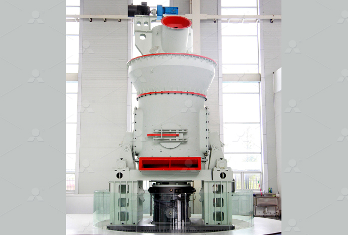
LM Vertical Roller Mill
Input size:38-65mm
Capacity: 13-70t/h
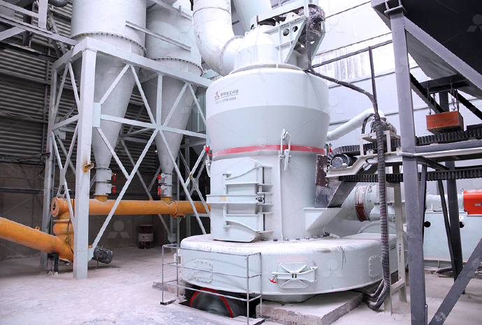
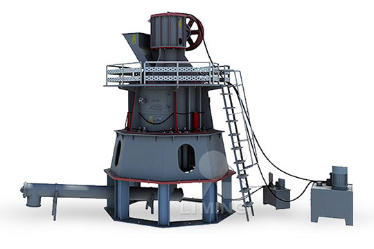
Raymond Mill
Input size:20-30mm
Capacity: 0.8-9.5t/h
Sand powder vertical mill
Input size:30-55mm
Capacity: 30-900t/h
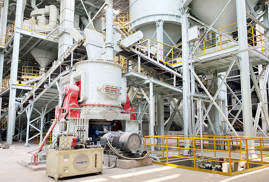
LUM series superfine vertical roller grinding mill
Input size:10-20mm
Capacity: 5-18t/h
MW Micro Powder Mill
Input size:≤20mm
Capacity: 0.5-12t/h

LM Vertical Slag Mill
Input size:38-65mm
Capacity: 7-100t/h

LM Vertical Coal Mill
Input size:≤50mm
Capacity: 5-100t/h
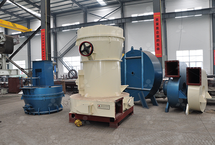
TGM Trapezium Mill
Input size:25-40mm
Capacity: 3-36t/h
MB5X Pendulum Roller Grinding Mill
Input size:25-55mm
Capacity: 4-100t/h
Straight-Through Centrifugal Mill
Input size:30-40mm
Capacity: 15-45t/h
Electrical principle circuit diagram of plc transformation of fire shutter door electrical control system
.jpg)
PLC Automatic Door Control System – Programming Example
Problem Description Implement logic for the automatic door open close system in PLC using ladder diagram programming language 展开 paper adopts the photoelectric sensor to collect whether the object passes the signal to the PLC, and controls the opening and closing of the automatic door through the inverter, theSchematic diagram of the automatic door control systemThe basic principle of automatic door control system is to use PLC to output digital signal and analog signal to inverter to change working power frequency and drive motor steering, drive Design of PLC Control System for Automatic DoorThe power circuit consists of an MCB, Contactors, and a motor The control circuit consists of Pushbuttons, limit switches, and contactor coils In the power circuit, the MCB is powered ON Shutter Door Control using Motor and Limit Switches Inst Tools
Electrical Drawings, Schematics, and Wiring Diagrams: How to
2024年1月15日 These diagrams are most commonly heard in control circles when referring to one of the PLC IEC 61131 languages, FBD However, they are also used to define a An electrically operated rolling shutter usually has a standard control panel with a threeposition switch: up, down and stop If you would like to automate the opening and closing with a time Rolling Shutter Motor Control Circuit Diagram Learning Electronics2016年1月1日 The principle of control system analyzed with verbal description of the control system hardware was introduced that the procedure of control circuits about human body Control System Design of Automatic Door Based on PLCWe have come across automatic door opening system in shopping malls; working of such automatic system using PLC based Door Open and Closing System Latching rung to operate PLC based Door Open and Closing System InstrumentationTools
Design of PLC Control System for Automatic Door 百度学术
The basic principle of automatic door control system is to use PLC to output digital signal and analog signal to inverter to change working power frequency and drive motor steering, drive In this session, we look at how to put all the components of the Signals and Systems unit together We’ll model complex systems by breaking them down into smaller systems and Designing Control Systems Introduction to Electrical Engineering 2024年1月15日 The engineering world is crammed full of drawings and diagrams of every possible kind System level function blocks, physical 3D models and prints, piping and instrument diagrams (pids), wiring diagrams, Electrical Drawings, Schematics, and Wiring Diagrams: 2012年2月24日 Circuit Diagram Importance: Understanding the circuit diagram of an electronic ballast is crucial as it includes components like EMI filters and rectifiers that ensure efficient operation Advantages of Using Electronic Electronic Ballast: Working Principle Circuit Diagram
.jpg)
MOTOR CIRCUITS AND CONTROL – Applied
102 Contactors All About Contactors Figure 105 When a relay is used to switch a large amount of electrical power through its contacts, it is designated by a special name: contactorContactors typically have multiple contacts, and those 2017年9月20日 How To Read A Plc Wiring Diagram Control Panel Upmation Plc Discrete Input And Output Devices The Engineering Knowledge Engineering Proceedings Free Full Text An Effective Combination Of Plc And Microcontrollers For Centralized Traffic Control Monitoring System Html Plc Programmable Logic Control Block Diagram Input Output Modules D E Plc Internal Circuit Diagram Wiring Digital and Schematic2020年1月1日 Electrical control circuit design plays an important role in electrical engineering projects Good design of electric control circuit will be beneficial to the orderly operation of power systemApplications Research of Electrical Control Circuit DesignIn the power circuit, the MCB is powered ON and the supply goes to the contactor and in the control circuit, the Shutter is on the top side so it makes contact with the Limit switch 1 (UP) Then the Down button in the control circuit is pressed, which makes the Contactor 1 coil energize which makes the Contactor 1 activate, So the motor starts to rotate in a clockwise rotationShutter Door Control using Motor and Limit Switches Inst Tools

Circuit Theory Electrical4U
Circuit theory is the cornerstone of electrical engineering, providing the rules and methods for analyzing electrical circuits This page delves into the principles of circuit analysis, including Kirchhoff’s laws, Thevenin’s theorem, and Norton’s theoremPDF On Apr 15, 2017, Prof Omkar M Shete and others published Design Control of an Elevator Control System using PLC Find, read and cite all the research you need on ResearchGateDesign Control of an Elevator Control System using PLCOf course, we only have these switches on the panel door connected to the PLC and the rest of the sensors and actuators will be connected to the PLC once we install this control panel in the field The EmergencyStop that we have on the door is connected to the PLC digital input card as it only sends an on and off signal to the PLC input Basics of an Electrical Control Panel (Practical Example)This exact same principle applies to relay ladderlogic programming in electronic control systems called PLCs (Programmable Logic Controllers) In a PLC, a digital microprocessor performs the logic functions traditionally provided by electromechanical relays, with the programming for this microprocessor taking the form of a relay diagram (also called a “ladder logic” diagram)Relay Circuits and Ladder Diagrams Relay Control Systems
Block diagram of programmable logic controller (PLC)
2017年4月24日 The processor section is brain of PLC which consists of RAM, ROM, logic solver and user memory The central processing unit is heart of PLC CPU controls monitors and supervises all operation within PLC The CPU 2022年11月30日 This paper analyses and explores the principle and practical application of PLC in the field of electrical automation engineering, and optimises the automatic control system based on PLC(PDF) Research on the application of PLC technology As switching devices, they exhibit simple “on” and “off” behavior with no intermediate states Relays are very useful devices, as they allow a single discrete (on/off) electrical signal to control much greater levels of electrical The Basics of Control Relays Relay Control Systems Electrical schematics are essential tools for understanding and working with electrical circuit diagrams These diagrams, also known as circuit schematics or wiring diagrams, provide a visual representation of an electrical system or circuit By deciphering these schematics, beginners can gain valuable insights into how different components are Understanding Electrical Schematics: A Beginner’s Guide
.jpg)
Hydraulics and Electrical Control of Hydraulic Systems
Book Description Covers hydraulics math, Pascal’s Law, hydraulic schematics, fluid properties, series and parallel hydraulic circuits, regenerative extension, accumulators, flow control valves and flow control methods, pressure control valves, Carbon Monoxide Detectors Carbon monoxide detector is also known as CO detector It is an electronic device which contains on different types of sensors used to measure and sense the amount of carbon monoxide gas in the air When the level of carbon monoxide (it is a poisonous gas produced by combustion) crosses the specified limit, it indicates and triggers the fire alarm Types of Fire Alarm Systems and Their Wiring Diagrams2020年8月19日 Learn what a Control System mean and gain insights on its simplified introduction to Control Systems Understand the contrast between Open and Closed Loops and the pivotal role of feedback in system controlIntroduction to Control Systems 11 CircuitBread2021年1月1日 The measurement range of each object is shown in Table 1 In this paper, the S71200 series PLC is selected as the core controller of the control system to complete the status monitoring and data Design of Intelligent Feeding Control System Based on S71200 PLC
.jpg)
Application of PLC technology in electrical automatic control
2020年11月1日 The application of PLC control system in tapping machine can control production process by receiving digital or analog input signals , outputting digital or analog signals and executing various Design of PLC Control System for Automatic Door Jiangshan Gao, Yan Zhi College of Mechanical and Control Engineering, Guilin University of Technology, Guilin, China Abstract The core of automatic door is its control system The basic principle of automatic door control system is to use PLC to output digital signal and analogDesign of PLC Control System for Automatic Door2021年3月14日 Scalability: PLC systems can be expanded by adding more modules Ease of Maintenance and Troubleshooting: PLCs often have diagnostic functions and are easier to troubleshoot than traditional control systems Basic Introduction to PLCs: Understanding the Basics2018年12月27日 Transformers are vital components in electrical engineering, playing a key role in the transmission and distribution of electric power This page offers a thorough exploration of transformer principles, including their Transformer Electrical4U

Designing Control Systems Introduction to Electrical
Chapter 5: Signals and Systems (PDF 17MB) Lecture Video Watch the lecture video The handout and slides present the same material, but the slides include answers to the inclass questions Lecture 6: Designing Control Systems; 2024年3月19日 PLC system is a flexible, programmable electrical control equipment, because of its powerful, easy to use, high reliability characteristics, often used as the field data acquisition and equipment (PDF) Design of PLC Electrical Control System ResearchGateElectric Locomotives, though high on electrical engineering, work on the single principle of drawing current from external sources and then after sufficiently “modifying” it, feed it to the traction motorsHow Electric Locomotives (Electric Trains) Work?2023年1月1日 The temperature status of the thermostats is used to switch OFF or ON electric heaters in a bid to reduce or increase the temperature of a system The PLC technology enables continuous monitoring Design of a PLC Based Temperature Controlled System
.jpg)
Design of PLC Control System for Automatic Door ResearchGate
Schematic diagram of the automatic door control system I/O points, the input and output addresses are reasonably distributed, and the terminal wiring diagram is drawn, which is beneficial to the 8 Electrical and electronic principles Criteria Range Resource identified 81 Principles of electrical and electronic systems Flow of electrons8 Electrical and electronic principles Institution of Engineering 2019年1月1日 The paper analysed the characters of 29inch panel wash process in a color picture tube enterprise, and introduced the control system design of the multisection based 29inch panel wash machineDesign of PLC Control System for Automatic Door ResearchGateSystems 4 NFPA 92A Smoke Control Systems in Malls, Atria, and Large Areas NFPA 90A and 92A provide information on the use of smoke detectors in ducts of HVAC systems and smoke control systems 5 NFPA 101 Life Safety Code NFPA 101 specifies the requirements for smoke detection in both new and existing buildings depending on the type of occupancyOverview of Fire Alarm and Detection Systems CED Engineering

Electrical Drawings, Schematics, and Wiring Diagrams:
2024年1月15日 The engineering world is crammed full of drawings and diagrams of every possible kind System level function blocks, physical 3D models and prints, piping and instrument diagrams (pids), wiring diagrams, 2012年2月24日 Circuit Diagram Importance: Understanding the circuit diagram of an electronic ballast is crucial as it includes components like EMI filters and rectifiers that ensure efficient operation Advantages of Using Electronic Electronic Ballast: Working Principle Circuit Diagram102 Contactors All About Contactors Figure 105 When a relay is used to switch a large amount of electrical power through its contacts, it is designated by a special name: contactorContactors typically have multiple contacts, and those MOTOR CIRCUITS AND CONTROL – Applied 2017年9月20日 How To Read A Plc Wiring Diagram Control Panel Upmation Plc Discrete Input And Output Devices The Engineering Knowledge Engineering Proceedings Free Full Text An Effective Combination Of Plc And Microcontrollers For Centralized Traffic Control Monitoring System Html Plc Programmable Logic Control Block Diagram Input Output Modules D E Plc Internal Circuit Diagram Wiring Digital and Schematic

Applications Research of Electrical Control Circuit Design
2020年1月1日 Electrical control circuit design plays an important role in electrical engineering projects Good design of electric control circuit will be beneficial to the orderly operation of power systemIn the power circuit, the MCB is powered ON and the supply goes to the contactor and in the control circuit, the Shutter is on the top side so it makes contact with the Limit switch 1 (UP) Then the Down button in the control circuit is pressed, which makes the Contactor 1 coil energize which makes the Contactor 1 activate, So the motor starts to rotate in a clockwise rotationShutter Door Control using Motor and Limit Switches Inst ToolsCircuit theory is the cornerstone of electrical engineering, providing the rules and methods for analyzing electrical circuits This page delves into the principles of circuit analysis, including Kirchhoff’s laws, Thevenin’s theorem, and Norton’s theoremCircuit Theory Electrical4UPDF On Apr 15, 2017, Prof Omkar M Shete and others published Design Control of an Elevator Control System using PLC Find, read and cite all the research you need on ResearchGateDesign Control of an Elevator Control System using PLC
Basics of an Electrical Control Panel (Practical Example)
Of course, we only have these switches on the panel door connected to the PLC and the rest of the sensors and actuators will be connected to the PLC once we install this control panel in the field The EmergencyStop that we have on the door is connected to the PLC digital input card as it only sends an on and off signal to the PLC input This exact same principle applies to relay ladderlogic programming in electronic control systems called PLCs (Programmable Logic Controllers) In a PLC, a digital microprocessor performs the logic functions traditionally provided by electromechanical relays, with the programming for this microprocessor taking the form of a relay diagram (also called a “ladder logic” diagram)Relay Circuits and Ladder Diagrams Relay Control Systems