


MTW European Type Trapezium Mill
Input size:30-50mm
Capacity: 3-50t/h
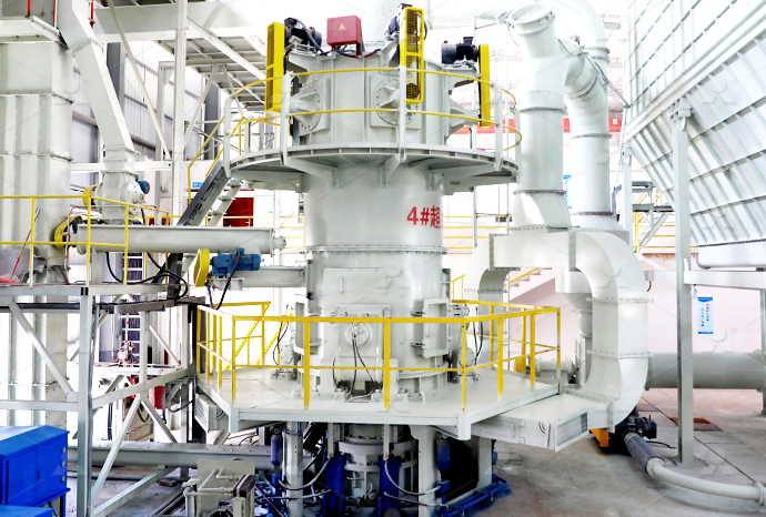
LM Vertical Roller Mill
Input size:38-65mm
Capacity: 13-70t/h
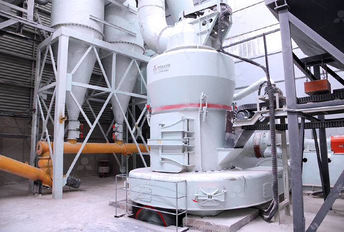
Raymond Mill
Input size:20-30mm
Capacity: 0.8-9.5t/h

Sand powder vertical mill
Input size:30-55mm
Capacity: 30-900t/h
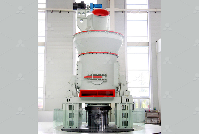
LUM series superfine vertical roller grinding mill
Input size:10-20mm
Capacity: 5-18t/h
MW Micro Powder Mill
Input size:≤20mm
Capacity: 0.5-12t/h

LM Vertical Slag Mill
Input size:38-65mm
Capacity: 7-100t/h

LM Vertical Coal Mill
Input size:≤50mm
Capacity: 5-100t/h
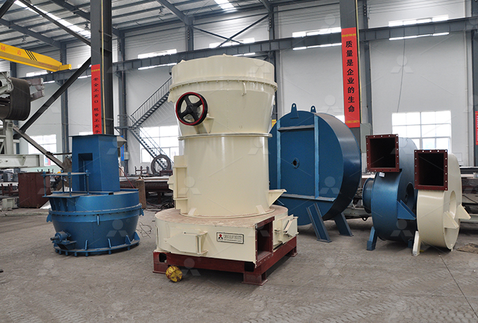
TGM Trapezium Mill
Input size:25-40mm
Capacity: 3-36t/h

MB5X Pendulum Roller Grinding Mill
Input size:25-55mm
Capacity: 4-100t/h
Straight-Through Centrifugal Mill
Input size:30-40mm
Capacity: 15-45t/h
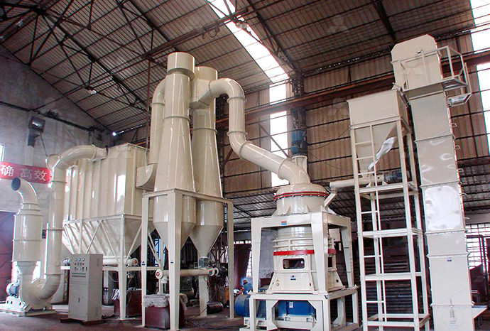
Hydraulic control circuit diagram of barite grinding machine

Hydraulic Circuit for Surface Grinding Machine
The hydraulic circuit of the surface grinding machine utilizes a power pack to supply pressurized oil, one pilotoperated direction control valve which decides the direction of the flow of pressurized oil, and a doubleacting cylinder with All hydraulic units and their connections must be shown on the circuit diagram The hydraulic schematic forms the basis of the pipework of the system and –– together with the function Circuit diagram HAWE Hydraulik2019年2月4日 Typical hydraulic circuits for control of industrial machinery are described in this lesson Graphical hydraulic circuit diagrams incorporating component symbols are used to INDUSTRIAL HYDRAULIC CIRCUITS IDCOnlineFig163 illustrates a typical hydraulic circuit used in a surface grinding machine This circuit uses 4/2 pilot operated DC valves, 2 limit valves (LV 1 and LV 2 ), a flow control valve and a doublerod end cylinderHydraulic circuit for a surface grinding machine

sbm/sbm grinding circuit baritemd at main chengxinjia/sbm
Contribute to chengxinjia/sbm development by creating an account on GitHub2017年8月21日 Hydraulic circuit consist of a set of hydraulic components that performed a designed task During the hydraulic circuit design, three factors must be considered: 1 Safety Hydraulics Pneumatics Chapter 1: Hydraulics (Circuit 3 天之前 was developed In this series, "Hydraulics − Basic principles" offers an overview of the basic principles and components of hydraulic systems such as on/off valves, hydraulic pumps, Compact knowledge Hydraulics – Basic principles2013年5月6日 Industrial Machinery Manuals Is Proud To Offer 1 Quality Full Size Hydraulic Circuit Diagram: Norton 10" Type CTU Cylindrical Grinding Machine Hydraulic Circuit » hydraulic layout circuit for grinding machine Grinding Mill
.jpg)
INDUSTRIAL HYDRAULIC CIRCUITS IDCOnline
2019年2月4日 • Interpret hydraulic system symbols and circuit diagrams • Describe techniques for energy saving in hydraulic systems Introduction Typical hydraulic circuits for control of industrial machinery are described in this lesson Graphical hydraulic circuit diagrams incorporating component symbols are used to explain the operation of the circuits2018年3月24日 A basic hydraulic circuit diagram is a graphical representation of a system of interconnected mechanical components, known as actuators and pumps, that transfer energy through a medium complex underground drill Basic Hydraulic Circuit DiagramThe hydraulic circuit for a milling machine is comparatively different from the hydraulic circuit of the surface grinding machine and hydraulic circuit of the shaper machineThis is because the table movement in milling operation is Hydraulic Circuit for Milling Machine Explained 2023年5月18日 8 Explain the speed control circuit for hydraulic motor Figure shows a circuit where speed control of a hydraulic motor ( Bi directional motor) is accomplished using a flow control valve to control the fluid flow to the motor In the springcentered position of the tandem fourway valve, the motor is hydraulically lockedLECTURE 24 TO 26 HYDRAULIC CIRCUIT DESIGN
Hydraulic Circuit (System) Parts, Application, Advantages,
1 天前 Introduction to Hydraulic Circuit (System) Hydraulic System: The controlled movement of parts or a controlled application of force is a common requirement in the industries These operations are performed mainly by using electrical machines or diesel, petrol, and steam engines as prime moversSchematic diagram hydraulic system A hydraulic system is an essential component of many industrial and mobile machines It uses the power of fluid to transmit and control energy This system consists of various components such as a hydraulic pump, control valves, hydraulic cylinders, and fluidsThe Ultimate Guide to Understanding Schematic Diagrams of Hydraulic 2018年10月26日 A hydraulic circuit represents all the hydraulic components in a system This includes the arrangement of the components and the behavior of the system as a A direction control valve is a vital component in a hydraulic system It controls the actuator’s position and direction by controlling the fluid flow into the actuator Therefore A guide to common hydraulic symbols Mechanical 2017年9月23日 The hydraulic circuit diagram is a key tool that allows engineers to effectively control a mill which can be operated by hydraulic actuators This diagram breaks down the construction and function of each part within the system, and shows the flow of fluid to the actuators Essentially, the hydraulic circuit controls the movement of the milling Hydraulic Circuit Diagram For Milling Machine

Hydraulic Circuit Diagram Of Injection Molding Machine
2018年6月8日 Hydraulic circuits are used to control the pressure of the hydraulic fluid, allowing it to go where it is needed in order to complete certain tasks The hydraulic circuit diagram of an injection molding machine is a visual representation of all the components that make up the machine and how they interact with each otherGenerally speaking, hydraulic control systems can be divided into two different driving concepts The first one is the wellknown valvecontrolled system and the second one is the pumpcontrolled Schematic circuit diagram of a conventional hydraulic tube 2024年11月2日 Directional Control Valves Manual: Shown as a valve symbol with an actuator lever; Solenoid: Indicated by a square with a diagonal line and a circle at one end, representing the solenoid actuator; Pilotoperated: Hydraulic Schematic Symbols Piping 3 天之前 hydraulic fluids 296 4 Basic circuits of hydraulics 297 41 Circuit diagrams in hydraulics 297 411 Graphical illustration of hydraulic circuits 297 42 Open and closedloop control with valves 300 421 Openloop control with directional control valves 300 422 Velocity control with throttle valves 304Hydraulics Basic Principles Bosch Rexroth WE MOVE
.jpg)
Design of hydraulic pneumatic control system for rail grinding
2022年12月1日 Hydraulic control schematic diagram Working principle: First, open the main switch and connect the oil circuit The signal obtained by the twoposition, threeway reversing valve is placed in the 2017年10月3日 A mixer grinder circuit diagram is essentially a map of the electrical flow from the power supply through the device and on to the user Electrical Charts For Hydraulic Sausage Stuffer Wiring Diagram Panasonic Mx Ac400wra Service Manual Page 26 Manualslib Havells Premio I 750w Mixer Grinder With 3 Jar And Digital Control Timer Black Mixer Grinder Circuit Diagram2019年6月5日 2 Schematic shows simple circuit to control cylinder extension and retraction using a 4port, 3position spool valve Spooltype valves are widely used because they can be shifted to two, three, or more positions for routing fluid between different combinations of Basics of DirectionalControl Valves Power Motion2021年3月1日 Electrical control is by far the most popular type of automatic control used for industrial hydraulic applications As Figure 12 shows, an electrical control circuit consists of the following parts: 1) Input element(s) 2) Controller 3) Actuating mechanism(s) Figure 12 Breakdown of an electrical control circuitUnit Introduction to Electrical Control of Hydraulic Systems
.jpg)
Basic Diagrams and Systems Engineering Library
The control pressure pump supplies highpressure fluid for the hydraulic control system, brake pistons, lock piston, and the handcontrolled clutch operating piston The control pressure pump is a fixeddisplacement, axial piston type An adjustable relief valve is used to limit the operating pressure at the outlet of the pump ControlHydraulic Drive Controls Hydraulic Circuit Diagrams The circuit diagrams are used in hydraulics to show the components along with their interaction It a useful tool for the manufacturers and assemblers so that they can come to know how the components are to be connected Mechanics or technicians will be helped with it, that how the Hydraulic Drive Controls: Lesson 28 Hydraulic circuit diagrams Hydraulic circuit diagrams are commonly used in engineering and design to help understand and troubleshoot hydraulic systems Hydraulic control devices: Hydraulic control devices, such as switches, sensors, and gauges, are used to monitor and control the operation of the hydraulic system They provide feedback, regulate pressure, and ensure The Ultimate Guide to Understanding Basic Hydraulic Circuit DiagramsIt is used to limit the pressure in a hydraulic circuit by diverting excess fluid back to the reservoir Flow control valve: The flow control valve symbol is represented by a square with a line and an arrow indicating the flow direction It is used to Understand the Basics: Decoding Hydraulic
.jpg)
Hydraulic Circuit Diagram With Explanation
2023年3月21日 What is a Hydraulic Circuit Diagram? A hydraulic circuit diagram is a visual representation of a hydraulic system in which components are identified by symbols and connected with lines to show their relationship 3 天之前 4 Basic circuits 135 41 Circuit diagrams in hydraulics 135 411 Graphical illustration of hydraulic circuits 135 42 Valve control circuits 138 421 Control with directional control valves 138 422 Velocity control with throttle valves 144 423 Loadindependent velocity control with flow control valves 152Compact knowledge Hydraulics – Basic principlesNo headers Covers hydraulics math, Pascal's Law, hydraulic schematics, fluid properties, series and parallel hydraulic circuits, regenerative extension, accumulators, flow control valves and flow control methods, pressure control valves, pumps, and electrically controlled hydraulic systemsHydraulics and Electrical Control of Hydraulic Systems (Pytel)They are used to control the direction, pressure, and flow rate of the fluid, allowing for precise control and operation of various hydraulic components To effectively understand and analyze hydraulic systems, it is essential to be familiar with the various schematic symbols used to represent hydraulic valvesThe Ultimate Guide to Hydraulic Valve Schematic Symbols:
.jpg)
Hydraulic Systems Basics Toro
2012年1月24日 hydraulic control valve The valve shown in the illustration is a open center valve, meaning that the oil flow is returned to the Accurate diagrams of hydraulic circuits are essential to the technician who must repair it If you don’t understand how the system operates, it is very difficult to diagnose possible hydraulic problems A hydraulic circuit diagram, also known as a hydraulic schematic, is a graphical representation of the hydraulic system in a machine or equipment We have also discussed the importance of understanding the pressure and flow control in a hydraulic system and how it affects the overall performance of the excavator Additionally, we have Excavator Hydraulic Circuit Diagram in PDF Format2019年5月12日 Control of a DoubleActing Hydraulic Cylinder The circuit diagram to control doubleacting cylinder is shown in Fig 12 The control of a doubleacting hydraulic cylinder is described as follows: 1 When the 4/3 valve is in its neutral position (tandem design), the cylinder is hydraulically locked and the pump is unloaded back to the tank 2Control of a DoubleActing Hydraulic Cylinder Hydraulic 2022年6月8日 Reading a hydraulic schematic for the first time is a daunting and confusing thing There are so many symbols to identify and lines to keep track of I hope to impart to you a systematic approach to reading a hydraulic schematic The basic steps to reading a hydraulic schematic are: Identifying line typesThe Best Way to Read a Hydraulic Schematic Mentored
.jpg)
INDUSTRIAL HYDRAULIC CIRCUITS IDCOnline
2019年2月4日 • Interpret hydraulic system symbols and circuit diagrams • Describe techniques for energy saving in hydraulic systems Introduction Typical hydraulic circuits for control of industrial machinery are described in this lesson Graphical hydraulic circuit diagrams incorporating component symbols are used to explain the operation of the circuits2018年3月24日 A basic hydraulic circuit diagram is a graphical representation of a system of interconnected mechanical components, known as actuators and pumps, that transfer energy through a medium complex underground drill Basic Hydraulic Circuit DiagramThe hydraulic circuit for a milling machine is comparatively different from the hydraulic circuit of the surface grinding machine and hydraulic circuit of the shaper machineThis is because the table movement in milling operation is Hydraulic Circuit for Milling Machine Explained 2023年5月18日 8 Explain the speed control circuit for hydraulic motor Figure shows a circuit where speed control of a hydraulic motor ( Bi directional motor) is accomplished using a flow control valve to control the fluid flow to the motor In the springcentered position of the tandem fourway valve, the motor is hydraulically lockedLECTURE 24 TO 26 HYDRAULIC CIRCUIT DESIGN
.jpg)
Hydraulic Circuit (System) Parts, Application, Advantages,
1 天前 Introduction to Hydraulic Circuit (System) Hydraulic System: The controlled movement of parts or a controlled application of force is a common requirement in the industries These operations are performed mainly by using electrical machines or diesel, petrol, and steam engines as prime moversSchematic diagram hydraulic system A hydraulic system is an essential component of many industrial and mobile machines It uses the power of fluid to transmit and control energy This system consists of various components such as a hydraulic pump, control valves, hydraulic cylinders, and fluidsThe Ultimate Guide to Understanding Schematic Diagrams of Hydraulic 2018年10月26日 A hydraulic circuit represents all the hydraulic components in a system This includes the arrangement of the components and the behavior of the system as a A direction control valve is a vital component in a hydraulic system It controls the actuator’s position and direction by controlling the fluid flow into the actuator Therefore A guide to common hydraulic symbols Mechanical 2017年9月23日 The hydraulic circuit diagram is a key tool that allows engineers to effectively control a mill which can be operated by hydraulic actuators This diagram breaks down the construction and function of each part within the system, and shows the flow of fluid to the actuators Essentially, the hydraulic circuit controls the movement of the milling Hydraulic Circuit Diagram For Milling Machine
.jpg)
Hydraulic Circuit Diagram Of Injection Molding Machine
2018年6月8日 Hydraulic circuits are used to control the pressure of the hydraulic fluid, allowing it to go where it is needed in order to complete certain tasks The hydraulic circuit diagram of an injection molding machine is a visual representation of all the components that make up the machine and how they interact with each otherGenerally speaking, hydraulic control systems can be divided into two different driving concepts The first one is the wellknown valvecontrolled system and the second one is the pumpcontrolled Schematic circuit diagram of a conventional hydraulic tube