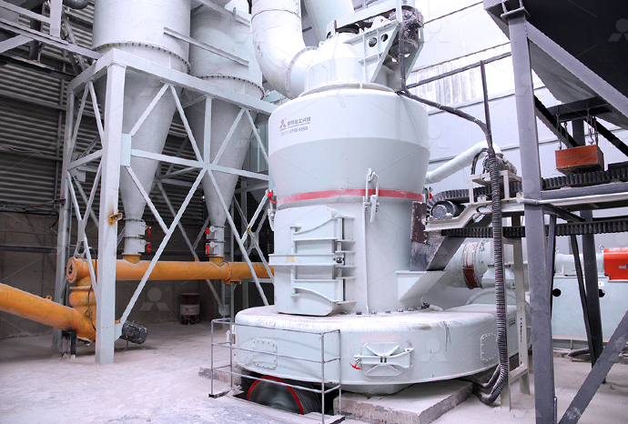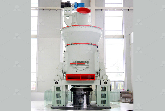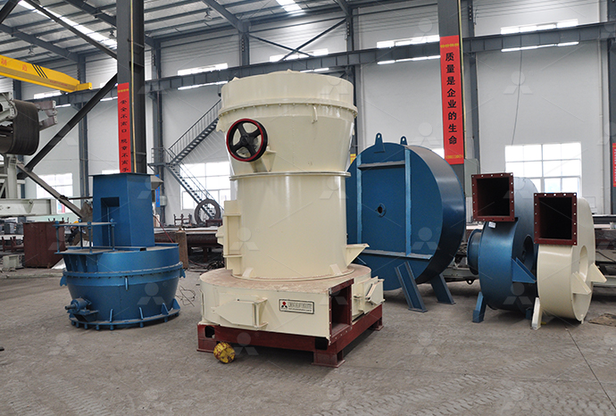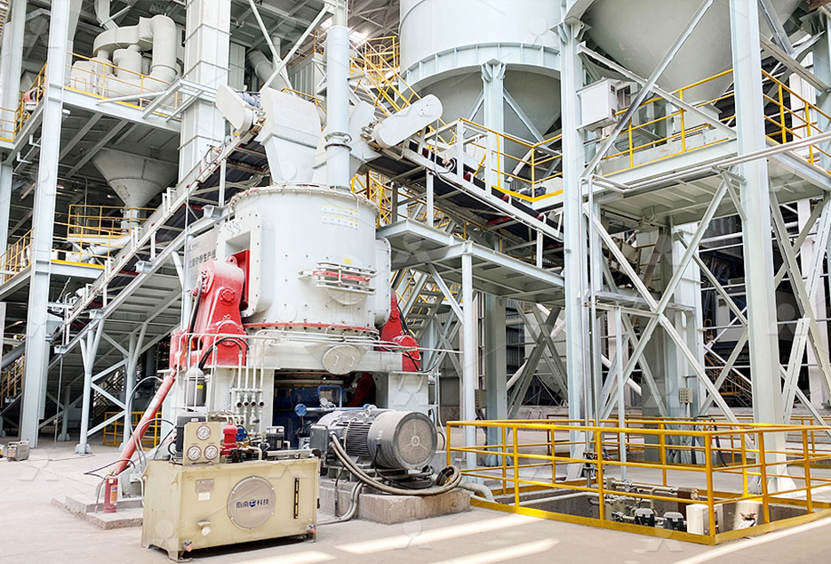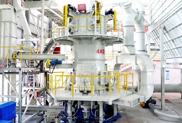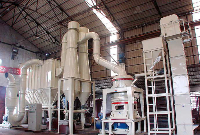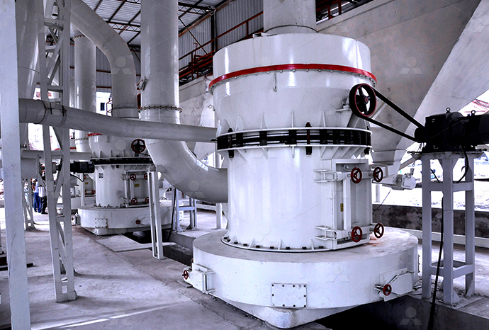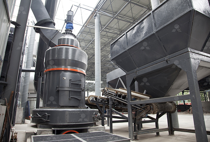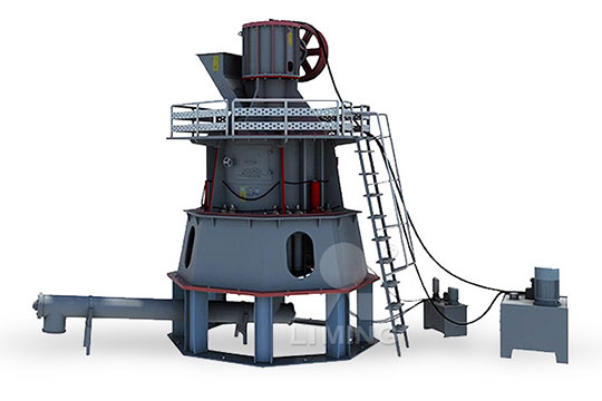
HOME→Straightthrough centrifugal mill structure diagram Straightthrough centrifugal mill structure diagram Straightthrough centrifugal mill structure diagram
Straightthrough centrifugal mill structure diagram Straightthrough centrifugal mill structure diagram Straightthrough centrifugal mill structure diagram
.jpg)
3: Centrifugal compressors (courtesy of DresserRand):
The proposed control structure with a GA tuned compressor characteristic is required to minimize system oscillations and energy losses induced by the piston actuation gas recycling technique2017年5月21日 The most fundamental configuration of a centrifugal compressor is the straightthrough design This layout is composed of one or more impellers, aligned in the same Types of centrifugal compressor configurations Turbomachinery Figure 169 shows a schematic diagram of a centrifugal compressor It consists of inlet (suction) pipe (1), an impeller (rotor) with blades or vanes (2), a vaned or vanless diffuser (3), a volute Centrifugal Compressors: Construction, Principle, Work 2016年5月26日 Layout of centrifugal compressor shown in Fig 91 defines three states, namely, the impeller inlet (state 1), impeller outlet (state 2), and diffuser outlet (state 3) These states Centrifugal and Axial Compressors SpringerLink
.jpg)
Centrifugal Compressor an overview ScienceDirect Topics
A centrifugal compressor is a kind of dynamic compressor that increases the fluid’s tangential velocity using rotary blades and converts it to pressure through the diffuser You might find overview of what components are within a centrifugal compressor, focusing on the flow path of the machine Subsequent articles will discuss general compressorCENTRIFUGAL COMPRESSORS CONSTRUCTION EXPLAINEDDownload scientific diagram Design of TM3 type centrifugal roller mill from publication: Mechanical pretreatment of corn straw in a centrifugal roller mill Processes takingDesign of TM3 type centrifugal roller mill ResearchGateOur broad range of centrifugal compressors, including both integrally geared and nongeared designs, provides innovative ways to handle the pressures you face every day Get the Driving Centrifugal Compressor Technology Atlas Copco
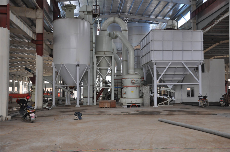
Horizontal Centrifugal Pump Structure Diagram
Horizontal centrifugal pump structure diagram (main points of construction and installation) 1) The following rechecks should be made before the pump is in place; the size, Measures should be taken to prevent sound transmission Download scientific diagram Structure of a semiopen impeller for a centrifugal compressor from publication: Experimental Investigation on Centrifugal Compressor Blade Crack Classification Structure of a semiopen impeller for a centrifugal Download scientific diagram a unique structure of centrifugal compressor in compressed flow rate and toothclearance pressure for liquidphase flow in the straightthrough labyrinth Geometry of the multistage centrifugal compressorCentrifugal casting is a metal casting process in which molten metal is poured into a rotating mold and solidifies under the influence of centrifugal force The centrifugal force helps to distribute the molten metal evenly and eliminate any air pockets or voids that might be present, resulting in a uniform and dense castingCentrifugal Casting EngineeringTechnology
.jpg)
Velocity Triangle or Diagram of Centrifugal Pump Work Done
The velocity triangle or velocity diagram of centrifugal pump along with basics, how to draw and work done of a centrifugal pump is explained If a liquid is flowing through a stationary pipe, this velocity will be absolute velocity It is normally denoted by V;Download scientific diagram Schematic diagrams of the centrifugal fan structure: (1) Centrifugal fan power input pulley (2) Fan blade (3) Centrifugal fan power output pulley Note: D0 is the Schematic diagrams of the centrifugal fan structure: (1) Centrifugal 2017年5月21日 The most fundamental configuration of a centrifugal compressor is the straightthrough design This layout is composed of one or more impellers, aligned in the same direction, contained within a single casing fitted with a single inlet nozzle and a single discharge nozzle to accommodate the gas flowTypes of centrifugal compressor configurations2022年9月30日 The fluid in a centrifugal pump enters the casing, falls on the impeller vanes at the impeller eye, and rotates radially outward until it exits the impeller through the diffuser (volute) of the casing As it passes through the impeller, the fluid gains both velocity and pressure Flow passage through a centrifugal pump (Reference: facebook)Centrifugal Pump Working Principle with Diagram Linquip
Centrifugal Pump Working Principle with Diagram Linquip
pressure head causes the water to be transferred from one point to another It is a centrifugal force applying to the fluid that makes it flow inside the casing What is a Centrifugal Pump Centrifugal Pump is the common type of pump for transferring fluids Simply put, it uses a rotating impeller to move other fluids applying centrifugal forceLearn about Centrifugal Pump Diagram I will show you various centrifugal pumps with a schematic and crosssection to show you different parts insideCentrifugal Pump Diagram HardHat Engineer2021年3月11日 The structure diagram of singlesuction multistage segmented centrifugal pump includes horizontal segmented multistage centrifugal pump structure, horizontal selfbalancing multistage segmented centrifugal pump structure, vertical multistage segmented centrifugal pump structure, medium and low pressure boiler Multistage segmented centrifugal pump Singlesuction multistage segmented centrifugal pump structure diagram2024年6月26日 Centrifugal fans, also called Centrifugal blowers, play an essential role in various industrial applicationsYou will find them widely used in HVAC systems, manufacturing processes, dust collection, and more This comprehensive guide explores the mechanics, types, applications, and benefits of centrifugal fans, providing a detailed overview that highlights their importance Centrifugal Fans: An InDepth Exploration AS Engineers

What is a Centrifugal Pump? Working Principle, Parts,
The Centrifugal pump is the most widely used pump in the world In this article, we will learn the basic definition, parts, types, how does centrifugal pump works, various diagrams, etc It is a rotary pumpHere, flow and pressure are Download scientific diagram Centrifugal casting simulation model (a) Structure model and (b) grid model from publication: Simulation Study on Filling and Solidification of Horizontal Centrifugal casting simulation model (a) Structure model and (b) 2023年11月15日 Housing Structure in the Centrifugal Fan Diagram Examining the housing structure within the centrifugal fan diagram unveils its significance in directing and channeling airflow The diagram elucidates different housing configurations, showcasing how curvature, size, and shape influence air velocity and pressure changes as air traverses through the fanUnderstanding Centrifugal Fan Diagrams: Key Components and Centrifugal Pumps Centrifugal pumps are the most common type of pumps found in DOE facilities Centrifugal pumps enjoy widespread application partly due to their ability to operate over a wide range of flow rates and pump heads Introduction Centrifugal pumps basically consist of a stationary pump casing and an impeller mounted on a rotating Pumps Engineering Library

How To Make An Ethernet Cable (Crossover Straightthrough
2015年5月17日 Straightthrough means that the cable is wired equally in both ends The wires go from one pin number to the same pin number To make a straightthrough Ethernet cable you can use either T568A or T568B As long as you use the same standard in both ends of your cable If you are extending an existing network, you should always check which wire A quick and easy guide showing the difference in Straightthrough, Crossover, and Rollover wiring of cables and the intended use for each type of cable Computer Cable Store Help Contact us MonFri 8:30am5pm EST 8006266622 Live Chat Contact us Account Sign in New Customer Create Account 0 Cart; You have no items in your shopping Straightthrough, Crossover, and Rollover Wiring Computer These compressors can be arranged in a variety of configurations such as straightthrough, compound, and double flow configurations Multistage compressors are also available in beamtype designs However their impellers are located between the radial bearings of compressor Applications of Centrifugal Compressor 1 Food IndustryCentrifugal Compressor: Definition, Types, Working Principle PressureEnthalpy Diagram The PressureEnthalpy (PH) diagram is another way of looking at the refrigeration cycle It has the advantage of graphically showing the process, the cooling effect and the work required to make it happen Figure 2, Refrigeration Circuit, PH DiagramCentrifugal Chiller Fundamentals EnergyModels
What is Hammer Mill? Working Principle, Construction,
Working of Hammer Mill Feed is introduced from the top of the mill As the feed enters the grinding zone, it is size reduced by the swing hammers by beating From here, the particles are further size reduced by the action of stationary In this article we will discus about: 1 Construction and Principle of Operation of Centrifugal Compressor 2 Velocity Diagrams of a Centrifugal Compressor 3 Work Requirement (Euler's Work) 4 Slip Factor 5 Pressure Ratio of Compression 6 Influence of Impeller Blade Geometry 7 Influence of Compressor Geometry on the Performance 8 PreWhir 9 Losses Contents: Centrifugal Compressors: Construction, Principle, Work Requirement 2016年8月4日 Also, a proper simplified structure of the horizontal centrifugal casting mechanism is applied, which uses a highfrequency current for the heat of bimetallic bearings from steelbronzeCentrifugal casting technique baseline knowledge, Reciprocating Pump – Construction and Working animation Project Pedal Powered/Operated Centrifugal Pump (PPCP) Centrifugal Compressor – Diagam, Parts, Working, Efficiency, Advantages Fluid Mechanics Interview Questions with Answers For Mechanical Students Lobe Pump – Working , Advantages , Disadvantages , Application Francis Turbine – Diagram, Construction And Working Of Centrifugal Pump Parts Of Centrifugal Pump
.jpg)
Schematic of Centrifugal casting machine Download Scientific Diagram
Download scientific diagram Schematic of Centrifugal casting machine from publication: Production of CopperAluminum Bimetal by Using Centrifugal Casting and Evaluation of Metal Interface The 2021年3月12日 One, vertical segmental multistage centrifugal pump installation structure diagram from bottom in and top out The vertical segmental multistage centrifugal pump with bottom inlet and top outlet is an earlier multistage pump Although it is gradually decreasing, it is still widely used in some occasionsInstallation structure diagram of vertical segmented multistage Download scientific diagram (a) CVT structure; (b) Centrifugal belt pulley CVT structure from publication: CVT for a Small Electric Vehicle Using Centrifugal Belt Pulley In a conventional (a) CVT structure; (b) Centrifugal belt pulley CVT structureFind your centrifugal mill easily amongst the 36 products from the Retention time of 001 seconds ensure no heat gain No change in flavour or texture or colour or smell Shearing through centrifugal principle ensures no hammering High output optimal mash structure The C25 grinding mill was developed to mash apples and Centrifugal mill, Centrifugal grinding mill DirectIndustry
.jpg)
Centrifugal compressor PetroWiki
2015年6月1日 When intercooling is not needed, the arrangement is usually a straightthrough (inline) configuration For applications that require intercooling, the resulting twosection compressor may be configured in either an inline Fig 9—Example of centrifugal compressor processor flow diagram Download scientific diagram a Three kinds of centrifugal filter structure; b Centrifugal filter test platform layout diagram, fine particles may directly enter the system through filter poresa Three kinds of centrifugal filter structure; b Centrifugal filter 2011年4月3日 The centrifugal pump has a long history, its prototype was proposed as early as 1475, and the simple centrifugal pump appeared in 1680 The wide application of centrifugal pumps inevitably considers various energy consumption issues under various working conditions The structure diagram of centrifugal pumps is shown in Fig 1:Centrifugal Pump an overview ScienceDirect Topics2016年5月26日 Layout of centrifugal compressor shown in Fig 91 defines three states, namely, the impeller inlet (state 1), impeller outlet (state 2), and diffuser outlet (state 3) These states are also plotted on the T–S diagram in Fig 95 Centrifugal and Axial Compressors SpringerLink
Structure of the fivestage centrifugal pump with 1
Download scientific diagram Structure of the fivestage centrifugal pump with 1 shaft, 2 suction, 3 firststage impeller, 4 secondstage impeller, 5 vaneddiffuser, 6 discharge, 7 balance A centrifugal pump is a machine that uses rotational energy to transfer fluids and generate pressure It is widely used in various industries, such as agriculture, petroleum, and manufacturing Understanding the schematic diagram of a centrifugal pump is crucial for engineers and technicians in order to effectively operate and maintain the Understanding the Inner Workings of a Centrifugal Pump: A Schematic Diagram2000年12月1日 Investigation of phenol formaldehyde resins milling in centrifugal impact mills is presented The particle size distribution, energy consumption and size reduction ratio were observed at different Optimal particle acceleration in a centrifugal rotorimpact millDownload scientific diagram Centrifugal pump (drawing) from publication: Development of a predictive maintenance system for a centrifugal pump An approach is presented for the development of a Centrifugal pump (drawing) Download Scientific Diagram

(a) Diagram of a rice mill machine (b) The crosssection profile of
Download scientific diagram (a) Diagram of a rice mill machine (b) The crosssection profile of the milling chamber (c) A hexagonal rice sieve (d) A rotating roller consisting of a screw and A brief overview of the centrifugal pump’s basic anatomy, and how a centrifugal pump works Centrifugal Pump Types Learn the characteristics, advantages, and disadvantages of 8 of the most used centrifugal pump types Centrifugal Pump Terminology Definitions of a few terms about centrifugal pumps used in this bookTHE MUSTHAVE HANDBOOK FOR CENTRIFUGAL PUMPSbody through the feed port, under the action of centrifugal force, it is evenly distributed on the surface of the cylindrical body, and the rotating press roller extrudes and grinds the material under Roller Mill, Fig 1 Structure diagram of vertical roller mill 2 Roller MillRoller Mill SpringerDownload scientific diagram Pictorial view of the Centrifugal Pump from publication: Design, Production and Testing of a Single Stage Centrifugal Pump The design, construction and testing of a Pictorial view of the Centrifugal Pump Download Scientific Diagram


