


MTW European Type Trapezium Mill
Input size:30-50mm
Capacity: 3-50t/h
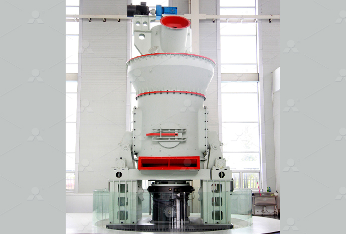
LM Vertical Roller Mill
Input size:38-65mm
Capacity: 13-70t/h
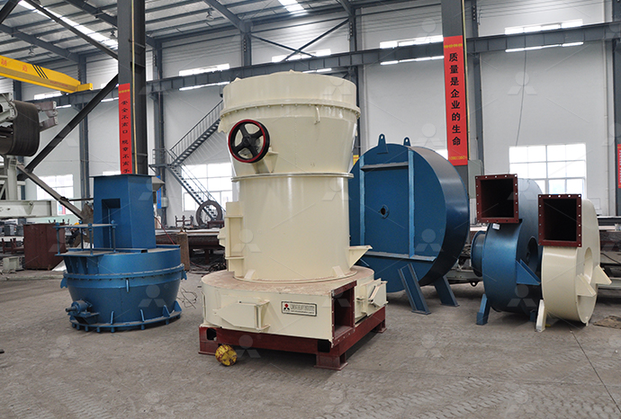
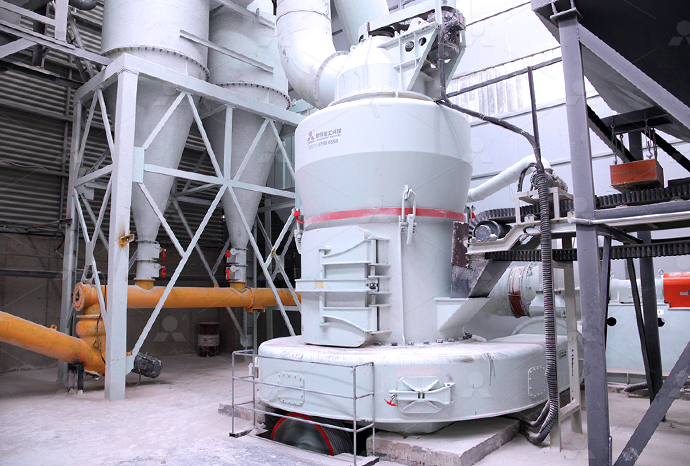
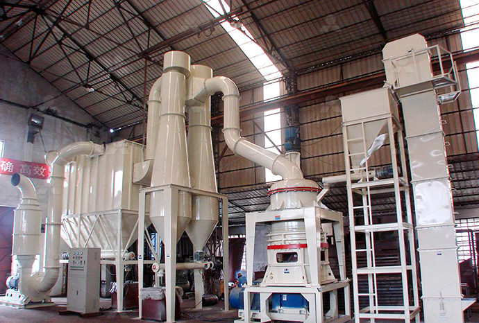
Raymond Mill
Input size:20-30mm
Capacity: 0.8-9.5t/h

Sand powder vertical mill
Input size:30-55mm
Capacity: 30-900t/h

LUM series superfine vertical roller grinding mill
Input size:10-20mm
Capacity: 5-18t/h
MW Micro Powder Mill
Input size:≤20mm
Capacity: 0.5-12t/h

LM Vertical Slag Mill
Input size:38-65mm
Capacity: 7-100t/h

LM Vertical Coal Mill
Input size:≤50mm
Capacity: 5-100t/h
TGM Trapezium Mill
Input size:25-40mm
Capacity: 3-36t/h

MB5X Pendulum Roller Grinding Mill
Input size:25-55mm
Capacity: 4-100t/h
Straight-Through Centrifugal Mill
Input size:30-40mm
Capacity: 15-45t/h
1 Ore grinding mill 380v AC contactor wiring diagram

Wiring Diagram TeSys Giga Series Giga Contactors and
Power Wiring Diagram; Installation of the Reverser Connection Kits; Control Wiring Diagram with Electrical Interlocking; Two Contactors Changeover Changeover Assembly Video; Mounting 2020年10月1日 Connect the external control wiring for the module to terminals 2, 3, and 4 on the module as shown on the wiring diagram (back page) Terminal 2 is not used on Accessory 47 Installation Maintenance E87010A0103T003A6 Understanding the schematic diagram of a contactor is important for troubleshooting and maintenance purposes It allows technicians to identify and locate faulty components, check the continuity of the circuit, and understand Understanding the Wiring Diagram of a 2023年1月4日 CJ20 series AC contactor (hereinafter referred to as contactor) is primarily used in AC 50Hz (or 60Hz) power system with rated voltage up to 660V (or 1140V) and current up CJ20 Series AC Contactor User Manual delixielectric
E87010A0105T003A6CLM0 Installation Sheet Siemens
2019年11月27日 Table 1 This industrial type contactor is designed to be installed, operated, and maintained by adequately trained personnel These instructions do not cover allSiemens Sirius contactor has two wire terminals, A1 and A2 This is where you connect a 24volt DC power source to the coil to energize it There are six additional wire terminals on the contactor’s opposite side L1, L2, and L3 are Siemens Contactor Wiring Diagram A Detailed 2024年2月13日 Identify the leads, match the incoming phase leads to the input terminals on the starter, then connect the outgoing motor leads to the output terminals on the starter Motor starters generally consist of two main How to Wire Motor Starters and Contactors2024年9月23日 wiring The contactor housing design effectively limits dust and other contaminants from the magnet structure, which 40 50 240 200 160 3 71/2 22 55 Definite purpose contactors and starters Eaton

GUIDE Contactors and Overload relays ABB
2024年3月23日 contactor range offers exceptional reliability and performance in a brilliant space saving design Use it for motor starting applications up to 750 A 400 V AC3, or for2023年4月18日 220v Ac Contactor Wiring Method And Physical Diagram Lc1 D40 Cjx2 4011 3p 4p Telemecanique Wiring Diagram Electrical Contactor China Ac Made In Com The Beginner S Guide To Wiring A Star Delta Circuit Factomart Singapore Contactor Wiring Diagram Electrical Wires Cable Relay Circuit Breaker Png 500x500px Alternating Cur CapacitorWiring A Contactor Diagram2024年2月18日 A contactor diagram helps in proper installation, reducing the chances of accidents or malfunctions 3 Understanding the Contactor Diagram A contactor diagram consists of various symbols and lines that represent different electrical components and their connections Here are some key elements you will find in a typical contactor diagram:Wiring a Contactor Diagram – A Comprehensive GuideThe wiring diagram of a 3 phase contactor reveals the arrangement of the wires and terminals that are used to connect the contactor to the power source and the load It also shows the use of overload relays and thermal protection devices, Schematic And Wiring Diagram Of 3 Phase
.jpg)
A Comprehensive Guide to Contactor Relay Wiring Diagrams
In this guide, we will walk you through the stepbystep process of wiring a contactor relay Step 1: Begin by gathering all the necessary tools and materials for the wiring process This may include a contactor relay, a power supply, control wires, electrical connectors, and a wiring diagram specific to your applicationWiring Diagrams 3 Pole Contactor with 1 NO base contact 3 Pole Contactor with 1 NC base contact 3 Pole Contactor without base contact 4 Pole Contactor with 4 NO Power Poles 4 Pole Contactor with 2 NO/2 NC Power Poles 3 Pole Reversing Contactor Set 4 Pole Control Relay with 4 NO contactsWiring Diagrams for Contactors, Motor Starters, Relays,2022年10月4日 A basic twopole contactor wiring diagram will typically include a power source, a switch or control relay, and the contactor itself The power source can be anything from a standard electrical socket to a solar panel, depending on the application The wiring diagram for a twopole contactor can also show the internal wiring within the 2 Pole Contactor Wiring Diagram » Wiring Diagram Wiring The wiring diagram for a single pole contactor typically consists of a power supply line, a control circuit, and a load circuit The power supply line, usually represented by L1 and L2, provides the voltage necessary to operate the contactor The control circuit, represented by a coil or a relay, controls the operation of the contactorWiring diagram for a single pole contactor explained
Contactor Wiring Diagram A1 A2 » Wiring Work Wiring
2023年1月12日 Electrical Contactor Connection And Wiring 1 Bbe Ac contactor for psu mains power general electronics arduino forum what is a working principles realpars helios air1 enh xh 2500 wiring diagram manualzz complete guide to contactors rs components self locking utmel volume 5 tab 2 usfull nlc1 d old type modular electric 25a 2p 2no china made in 2020年10月26日 220V AC contactor physical wiring diagram When the start button is pressed when starting, the control current from the power supply side will flow through the circuit breaker to the power line, then through the stop 220V AC contactor wiring method and physical 2022年6月1日 Wiring Diagram For Control Air Cooled Split Type Ac Unit Free Cad Block And Drawing 我愛拉霸機 2 Faema Velox 掛壁瞬熱式拉霸機 Mobile01 Rm Harrington Ductless Split Air Conditioner 3 Phase 4 Ton Outdoor Electric Split Ac Outdoor Contactor Wiring Diagram » The control circuitry includes the control switches or sensors that activate or deactivate the contactor When wiring a magnetic contactor for single phase systems, it is important to follow the manufacturer’s instructions and the wiring How to Wire a Magnetic Contactor in a Single
.jpg)
380V AC contactor installation physical wiring diagram
2020年10月26日 The wiring diagram of the 380V AC contactor is shown below First, connect the three phases of the power supply to the main contacts L1, L2, and L3 of the device in turn, and then connect three wires from the T1, T2, and T3 of the contactor to the three terminals of the motor The line is the main circuit2022年12月27日 The first step in connecting a 3 phase contactor is understanding the wiring diagrams Wiring diagrams show how electrical components of an electrical system are connected Wiring diagrams can tell you what wires will provide the power to the contactor, and which wires will control the contactorHow To Connect A 3 Phase Contactor » Wiring DiagramThe wiring diagram of a magnetic contactor for threephase systems typically includes various components, such as the power supply lines, control circuit, thermal overload relay, and motor The power supply lines deliver the threephase AC voltage to the contactor, while the control circuit consists of the start and stop buttons or switchesHow to Wire a Three Phase Magnetic Contactor: A Complete Diagram2023年1月6日 How To Wire A Contactor 8 Steps With Pictures Wikihow Volume 5 Tab 4 A9c20731 Schneider Electric Acti 9 Ict Contactor 230 V Ac Coil 1 Pole 25 A 1no Rs Components Outdoor Wiring With Magnetic Contactor Diagram Fully4world Pb Series Timer Wiring To Motor Control Earth Bondhon Contactor Diagram Electronics Forum Circuits ProjecticrocontrollersSingle Phase Contactor Wiring Diagram » Wiring Work
Schneider Electric Contactor Lc1d09 Wiring Diagram
2022年9月9日 The Schneider Electric Contactor LC1D09 Wiring Diagram enables designers and engineers to easily create reliable contactor systems that are capable of handling both AC and DC current Featuring multiple configuration options, this diagram allows users to quickly and accurately create contactor systems that are safe and effective2022年12月21日 Relay Contactor Driver Circuit Diagram Scientific Contactor Wiring Diagram Electrical Wires Cable Relay Circuit Breaker Png 500x500px Alternating Cur Capacitor Contactorotor Starters Plc Tutorial Point 220v Ac Contactor Wiring Diagram With Relay » Wiring A 380V 3phase wiring diagram is a graphical representation of the electrical connections and components used in a 3phase electrical system This type of system is commonly used in industrial and commercial settings, where a Understanding the Wiring Diagram for 380V 3 1 Incorrect wiring: One of the most common issues with contactor wiring is incorrect connections It’s important to doublecheck the wiring diagram provided by the manufacturer to ensure that the connections are made correctly Check the coil terminals, line terminals, and load terminals to make sure they are all properly connected 2Understanding the Wiring Diagram for a 3 Phase Contactor

3 Phase Contactor » Wiring Diagram
2022年12月26日 Understanding three phase contactor wiring diagrams is an important part of using these devices safely and correctly By having a good understanding of the wiring diagrams, electricians can ensure that their systems are correctly installed and maintained 18 Amps 3 Pole Ac Contactor 24v 110v 220v Coil Ato Com 3 Phase Motor Contactor Wiring 2023年4月26日 220v Ac Contactor Wiring Method And Physical Diagram Hager Esc 125 Contactor Switch Wiring Web Design Seo Company Star Delta Wiring Diagram Ideas For Android Is There Single Phase Contactor For Ac3 Application Schneider Electric Thailand Reversing Contactor Definition Advantages And Connection DiagramsContactor Circuit Diagram Wiring Digital and SchematicThis allows electricians and technicians to accurately install and troubleshoot the contactor The wiring diagram for a definite purpose contactor typically includes labels or symbols to indicate how each terminal should be connected It may also include information on the type and size of wires to use, as well as any additional components that How to Wire a Definite Purpose Contactor: A StepbyStep Guide with Diagram2023年1月30日 A contactor is an electrical device that is widely used for switching circuits on and off As such, electrical contactors form a subcategory of electromagnetic switches known as relays A relay is an electrically operated switching device that uses an electromagnetic coil to open and close a set of contacts This action results in a circuit powering either on or off A Complete Guide to Contactors RS Components
.jpg)
Contactor Wiring Diagram A1 A2 Wiring Digital and
2023年4月26日 Usfull Nlc1 D Ac Contactor Electrical Contactor Connection And Wiring 1 Bbe Contactor Overload Maintained Switch Wiring For Magnetic Motor Small Knowledge Of Contactor Wiring Diagram 1 3 5 Connected To Three Phase Power Supply Main Circuit Part 2 4 6 Motor A1 And A2 Are The Coils How To Wire A Contactor Talk Electrician ForumABB contactor wiring diagrams provide a visual representation of how the contactor should be connected to other components, such as power supplies, switches, and motors These diagrams depict the various terminals and connection points of the contactor, making it easier to understand the electrical connections required for functionalityA Complete Guide to Understanding Abb Contactor Wiring Diagrams1 Incorrect wiring connections: One of the most common issues with 3 phase contactor wiring is incorrect connections This can result in the contactor not functioning or operating in an unsafe manner It is important to carefully follow the wiring diagram provided by the manufacturer and doublecheck all connections before powering up the Wiring a ThreePhase Contactor: A StepbyStep Guide2023年4月18日 220v Ac Contactor Wiring Method And Physical Diagram Lc1 D40 Cjx2 4011 3p 4p Telemecanique Wiring Diagram Electrical Contactor China Ac Made In Com The Beginner S Guide To Wiring A Star Delta Circuit Factomart Singapore Contactor Wiring Diagram Electrical Wires Cable Relay Circuit Breaker Png 500x500px Alternating Cur CapacitorWiring A Contactor Diagram
Wiring a Contactor Diagram – A Comprehensive Guide
2024年2月18日 A contactor diagram helps in proper installation, reducing the chances of accidents or malfunctions 3 Understanding the Contactor Diagram A contactor diagram consists of various symbols and lines that represent different electrical components and their connections Here are some key elements you will find in a typical contactor diagram:The wiring diagram of a 3 phase contactor reveals the arrangement of the wires and terminals that are used to connect the contactor to the power source and the load It also shows the use of overload relays and thermal protection devices, Schematic And Wiring Diagram Of 3 Phase In this guide, we will walk you through the stepbystep process of wiring a contactor relay Step 1: Begin by gathering all the necessary tools and materials for the wiring process This may include a contactor relay, a power supply, control wires, electrical connectors, and a wiring diagram specific to your applicationA Comprehensive Guide to Contactor Relay Wiring DiagramsWiring Diagrams 3 Pole Contactor with 1 NO base contact 3 Pole Contactor with 1 NC base contact 3 Pole Contactor without base contact 4 Pole Contactor with 4 NO Power Poles 4 Pole Contactor with 2 NO/2 NC Power Poles 3 Pole Reversing Contactor Set 4 Pole Control Relay with 4 NO contactsWiring Diagrams for Contactors, Motor Starters, Relays,

2 Pole Contactor Wiring Diagram » Wiring Diagram Wiring
2022年10月4日 A basic twopole contactor wiring diagram will typically include a power source, a switch or control relay, and the contactor itself The power source can be anything from a standard electrical socket to a solar panel, depending on the application The wiring diagram for a twopole contactor can also show the internal wiring within the The wiring diagram for a single pole contactor typically consists of a power supply line, a control circuit, and a load circuit The power supply line, usually represented by L1 and L2, provides the voltage necessary to operate the contactor The control circuit, represented by a coil or a relay, controls the operation of the contactorWiring diagram for a single pole contactor explained2023年1月12日 Electrical Contactor Connection And Wiring 1 Bbe Ac contactor for psu mains power general electronics arduino forum what is a working principles realpars helios air1 enh xh 2500 wiring diagram manualzz complete guide to contactors rs components self locking utmel volume 5 tab 2 usfull nlc1 d old type modular electric 25a 2p 2no china made in Contactor Wiring Diagram A1 A2 » Wiring Work Wiring